Liquid crystal module

A technology of liquid crystal modules and LED light strips, which is applied in the direction of lighting and heating equipment, instruments, mechanical equipment, etc., can solve the problems of increasing manufacturing costs, achieve the effects of increasing manufacturing costs, high practicability, and solving light leakage on the light incident side

Inactive Publication Date: 2013-06-26
KONKA GROUP
View PDF4 Cites 4 Cited by
  • Summary
  • Abstract
  • Description
  • Claims
  • Application Information

AI Technical Summary

Problems solved by technology

[0008] Therefore, the technical problem to be solved by the present invention is to provide a liquid crystal module, which can effectively solve the problem of light leakage on the incident side of the l

Method used


Image

  • Liquid crystal module
  • Liquid crystal module
  • Liquid crystal module

Examples


Example Embodiment

[0023] Example one

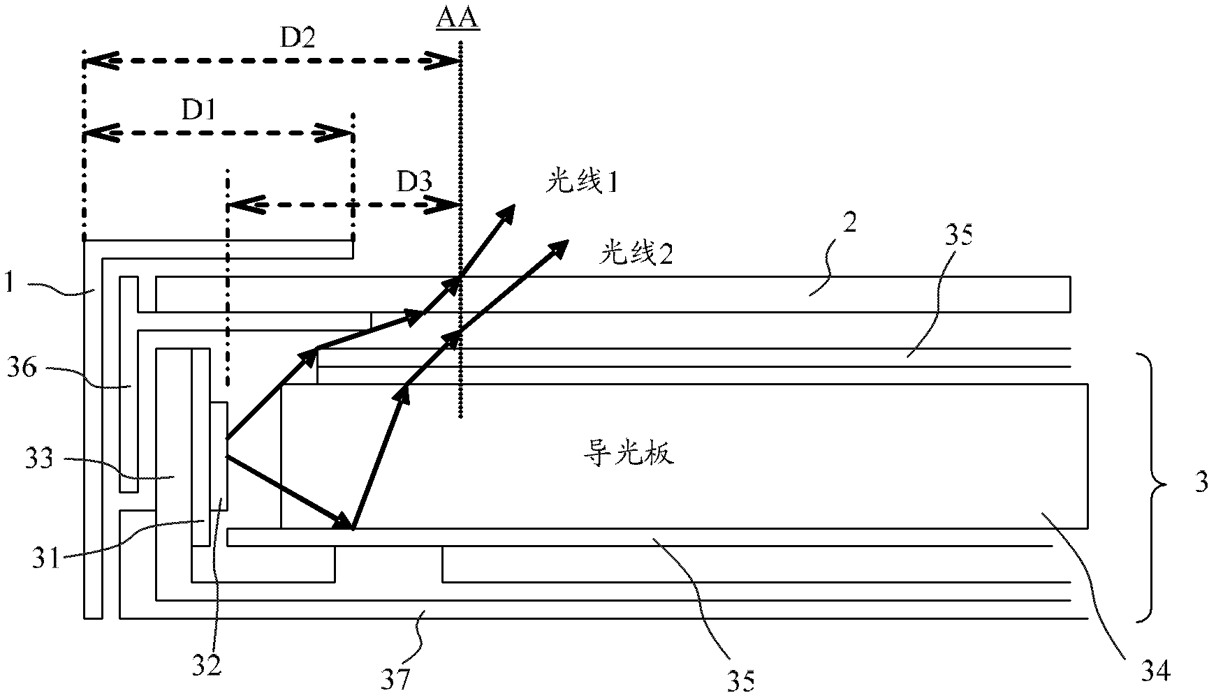
[0024] Such as figure 2 As shown, this embodiment provides a liquid crystal module including: a metal front frame 1, a liquid crystal panel 2 and a backlight module 5.

[0025] Among them, the backlight module 5 is an edge-type LED backlight module, including an LED light bar board 51, an LED lamp 52 placed on the LED light bar board, a heat sink 53, a light guide plate 54, and An optical film 55 that reflects light is placed above the light guide plate, a plastic frame 56 that supports the liquid crystal panel 2 and a back plate 57 that fixes and supports the components in the backlight module. The LED light bar board 52 on which the LED lights 52 are installed is called an LED light bar. The heat sink 33 is installed on the back of the LED light bar, and the LED light bar is placed around or on both sides of the light guide plate 34.

[0026] In this embodiment, the angle α between the LED lamp on the LED light bar and the bottom plane of the light guide pla...

Example Embodiment

[0028] Example two

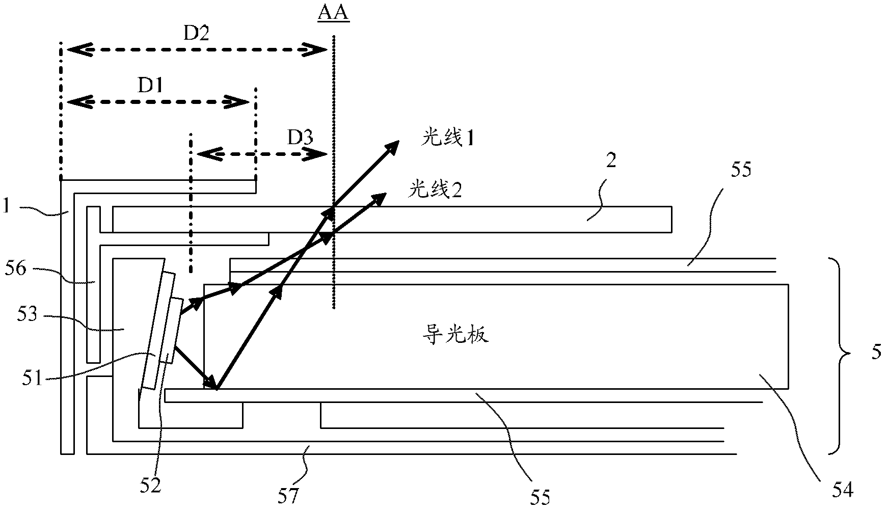
[0029] Such as image 3 As shown, the difference from the first embodiment is that in this embodiment, the LED light bar 51 is changed to a wedge-shaped structure, which can be realized by changing the thickness of the aluminum substrate on the LED light bar 51, that is, the LED The thickness of the aluminum substrate on the light bar board 51 is processed into a wedge-shaped structure.

Example Embodiment

[0030] Example three

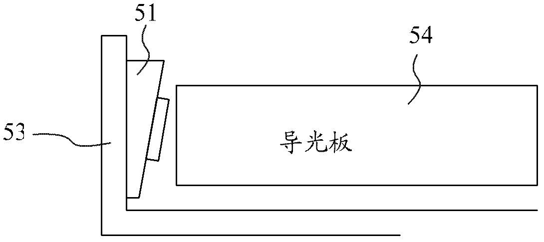
[0031] Such as Figure 4 As shown, the difference from the first embodiment is that in this embodiment, by adjusting the thickness of the adhesive coating 58 of the heat sink adhered to the LED light bar, the LED light on the LED light bar and the bottom plane of the light guide plate are realized. The angle between is less than 90 degrees. That is, the thickness of the adhesive coating is made uneven, and the angle between the LED lamp on the LED light bar and the bottom plane of the light guide plate can be less than 90 degrees.


PUM


Abstract

The invention provides a liquid crystal module which comprises a light guide plate, light-emitting diode (LED) lamp bars and cooling fins used for cooling the LED lamp bars, wherein the LED lamp bars are arranged on the periphery or on two sides of the light guide plate. The liquid crystal module is characterized in that included angles between the LED lamps on the LED lamp bars and a bottom plane of the light guide plate are smaller than 90 degrees. According to the liquid crystal module, the included angles between the LED lamps on the LED lamp bars and the bottom plane of the light guide plate are adjusted to be smaller than 90 degrees, a transmission path of light in the light guide plate is changed by changing an angle of the light of the LED lamp entering the light guide plate, the problem of light leakage on the incidence light side of the liquid crystal module in a narrow-frame liquid crystal television is effectively solved, so that on the premium that the assembly process of an existing liquid crystal module is not changed, manufacture cost is also not increased, and the liquid crystal module has high practicality.

Description

technical field [0001] The invention relates to the technical field of liquid crystal televisions, in particular to a liquid crystal module. Background technique [0002] Such as figure 1 As shown, the current liquid crystal module includes a metal front frame 1 , a liquid crystal panel 2 and a backlight module 3 . Wherein, the backlight module 3 is a side-entry LED backlight module, including an LED light bar 31, an LED light 32 placed on the LED light bar, a heat sink 33 for dissipating heat from the LED light, a light guide plate 34, a Above the light guide plate is an optical film 35 that reflects light, a plastic frame 36 that supports the liquid crystal panel 2 , and a back plate 37 that fixes and supports each component in the backlight module. The LED lamp 32 is vertical to the bottom plane of the light guide plate 34 and horizontal to the heat sink 33, that is, the angle between the LED lamp 32 and the bottom plane of the light guide plate 34 is 90 degrees, and th...

Claims


Application Information

Patent Timeline
IPC IPC(8): G02F1/13F21V8/00F21V17/00F21Y101/02F21Y103/00F21Y115/10G02F1/13357
Inventor 常文强
Owner KONKA GROUP
Why Eureka
Try Eureka