Eureka AIR delivers breakthrough ideas for toughest innovation challenges, trusted by R&D personnel around the world.

Tuned circuit and near-field payment equipment

A tuning circuit and near-field payment technology, which is applied in the field of oscillation tuning, can solve the problems of high cost, large circuit volume, and the output voltage of the resonant circuit cannot meet the rated demand, so as to reduce the circuit volume, reduce the tuning current leakage, and reduce the circuit cost effect

Active Publication Date: 2013-06-26
SHENZHEN NETCOM ELECTRONICS CO LTD
View PDF4 Cites 1 Cited by
  • Summary
  • Abstract
  • Description
  • Claims
  • Application Information

AI Technical Summary

Problems solved by technology

[0005] The purpose of the present invention is to provide a tuning circuit, aiming to solve the problem that the output voltage of the resonant circuit cannot meet the rated demand due to the tuning current leaking to the ground in the tuning circuit provided by the prior art, and there are problems of large circuit volume and high cost

Method used


Image

  • Tuned circuit and near-field payment equipment
  • Tuned circuit and near-field payment equipment
  • Tuned circuit and near-field payment equipment

Examples


Embodiment 1

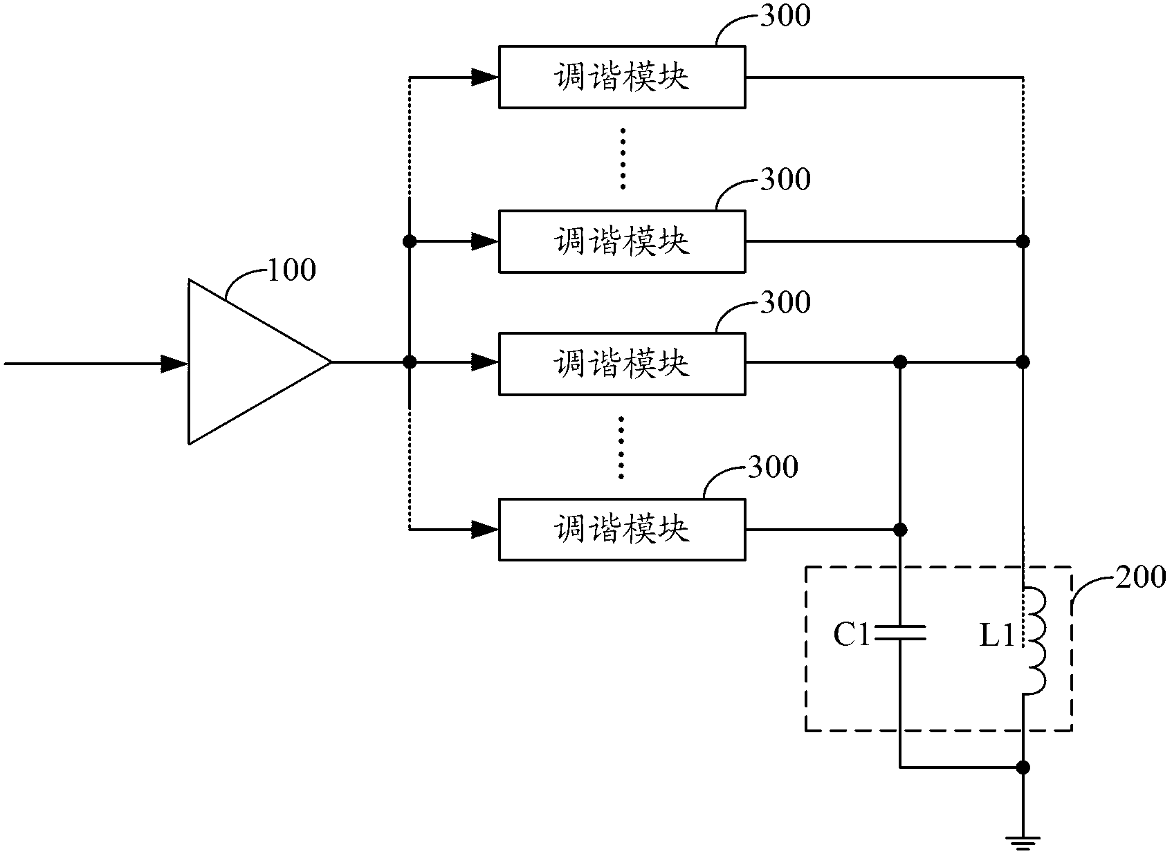
[0030] figure 2 The structure of the tuning circuit provided by the first embodiment of the present invention is shown. For the convenience of description, only the parts related to the present invention are shown, and the details are as follows:

[0031] The tuning circuit includes a signal input module 100 and a resonant circuit 200. The signal input module 100 is used to output a tuning current to the resonant circuit 200. The resonant circuit 200 includes a capacitor C1 and an inductor L1. The first end of the capacitor C1 is in common with the first end of the inductor L1. Grounded.

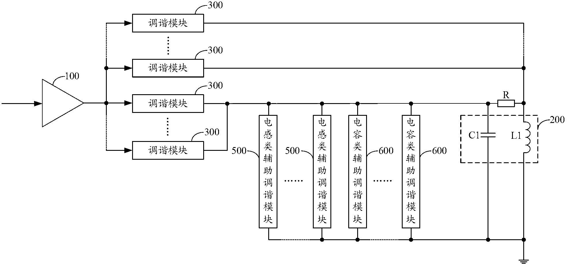
[0032] The tuning circuit further includes a plurality of tuning modules 300, and the number of the tuning modules 300 is a positive integer not less than 2.

[0033] The input end of each tuning module in the plurality of tuning modules 300 is connected to the output end of the signal input module 100, and the output end of each tuning module in the plurality of tuning modules 300 is simu...

Embodiment 2

[0051] Figure 6 The structure of the tuning circuit provided by the second embodiment of the present invention is shown. For the convenience of description, only the relevant parts of the present invention are shown. The details are as follows:

[0052] The tuning circuit includes a first signal input module 101, a second signal input module 102 and a resonant circuit 103, the first signal input module 101 and the second signal input module 102 respectively output the first tuning current and the second tuning current to the resonant circuit 103, The resonant circuit 103 includes a capacitor C11 and an inductor L11.

[0053] The tuning circuit further includes a plurality of first tuning modules 104 and a plurality of second tuning modules 105, and the number of the plurality of first tuning modules 104 and the plurality of second tuning modules 105 is a positive integer not less than 2.

[0054] The input terminals of the multiple first tuning modules 104 are all connected ...


PUM


Abstract

The invention belongs to the field of oscillation tuning and provides a tuned circuit and near-field payment equipment. By adopting the tuned circuit comprising multiple tuning modules, according to different switch choosing operations, tuning current is processed by one or more of the multiple tuning modules and transmitted to a resonance circuit, and resonance frequency of the tuning circuit is adjusted by cooperation of the processed turning current with a capacitor C1 and an inductor L1, so that the objective of reduction of tuning current leakage is achieved, the number of capacitors needed by the whole tuned circuit is decreased, the circuit size is further reduced, and circuit cost is lowered.

Description

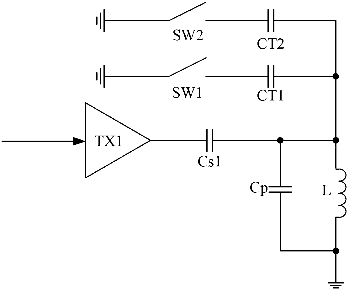
technical field [0001] The invention belongs to the field of oscillation tuning, in particular to a tuning circuit and near-field payment equipment. Background technique [0002] The tuning circuit is used for tuning, and the tuning purpose is achieved by adjusting the capacitance, inductance or resistance connected to the oscillating circuit before frequency acquisition, so that the oscillation can achieve a better effect. The resonant circuit in the tuned circuit can be a single tuned loop, or a double tuned loop coupled by two loops. [0003] The resonant circuit in the tuning circuit provided by the prior art includes a capacitor Cs1, a capacitor Cp and an inductor L, wherein one end of the capacitor Cs1 is grounded through the capacitor CT1 or the capacitor CT2 when the switch SW1 or the switch SW2 is closed (such as figure 1 shown). When the inductance L changes due to external influences, by controlling the switches SW1 and SW2 to connect the capacitors CT1 and CT2 ...

Claims


Application Information

Patent Timeline
IPC IPC(8): H03J3/22
Inventor 程振钟衍徽
Owner SHENZHEN NETCOM ELECTRONICS CO LTD
Why Eureka
Eureka Blog
Learn More