
Metal switch zipper and its manufacturing process

A manufacturing process and metal technology, applied in the field of metal switch zipper and its manufacturing process, can solve the problems of weak wire installation, poor circuit stability and high production cost, and achieve the advantages of reducing occupied space, long service life and simplifying production process. Effect

Active Publication Date: 2015-09-09
FUJIAN SBS ZIPPER SCI & TECH CO LTD
View PDF5 Cites 0 Cited by
  • Summary
  • Abstract
  • Description
  • Claims
  • Application Information

AI Technical Summary

Problems solved by technology

[0004] The invention provides a metal switch zipper and its manufacturing process to overcome the need for additional switch accessories in the existing non-mainstream clothing, high production costs, and inconvenient use; the existing metal switch zippers often have wires that are not installed firmly, It is easy to fall off or even twist off, which will cause problems such as poor circuit stability and short service life

Method used


Image

  • Metal switch zipper and its manufacturing process
  • Metal switch zipper and its manufacturing process
  • Metal switch zipper and its manufacturing process

Examples


Embodiment approach 1

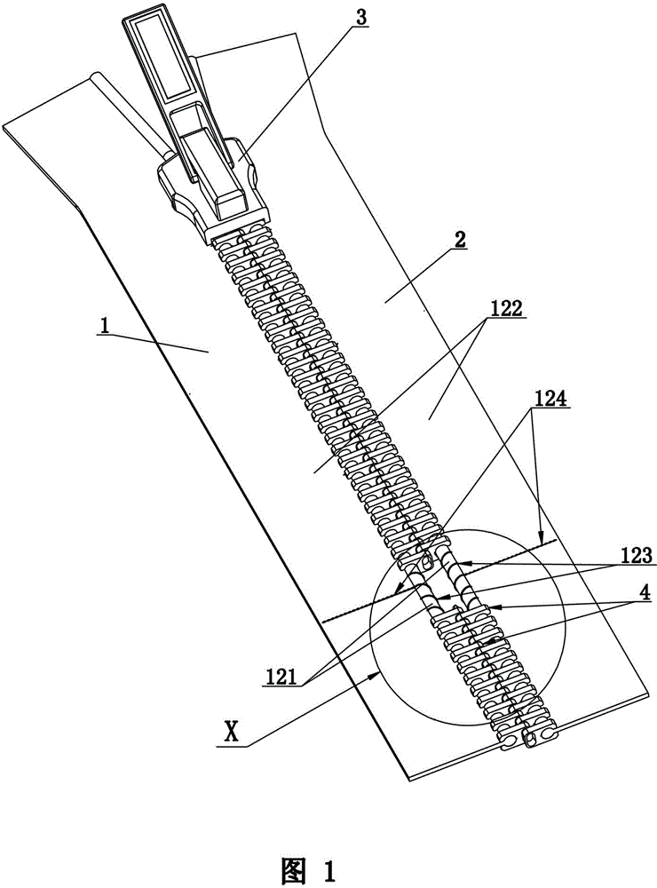
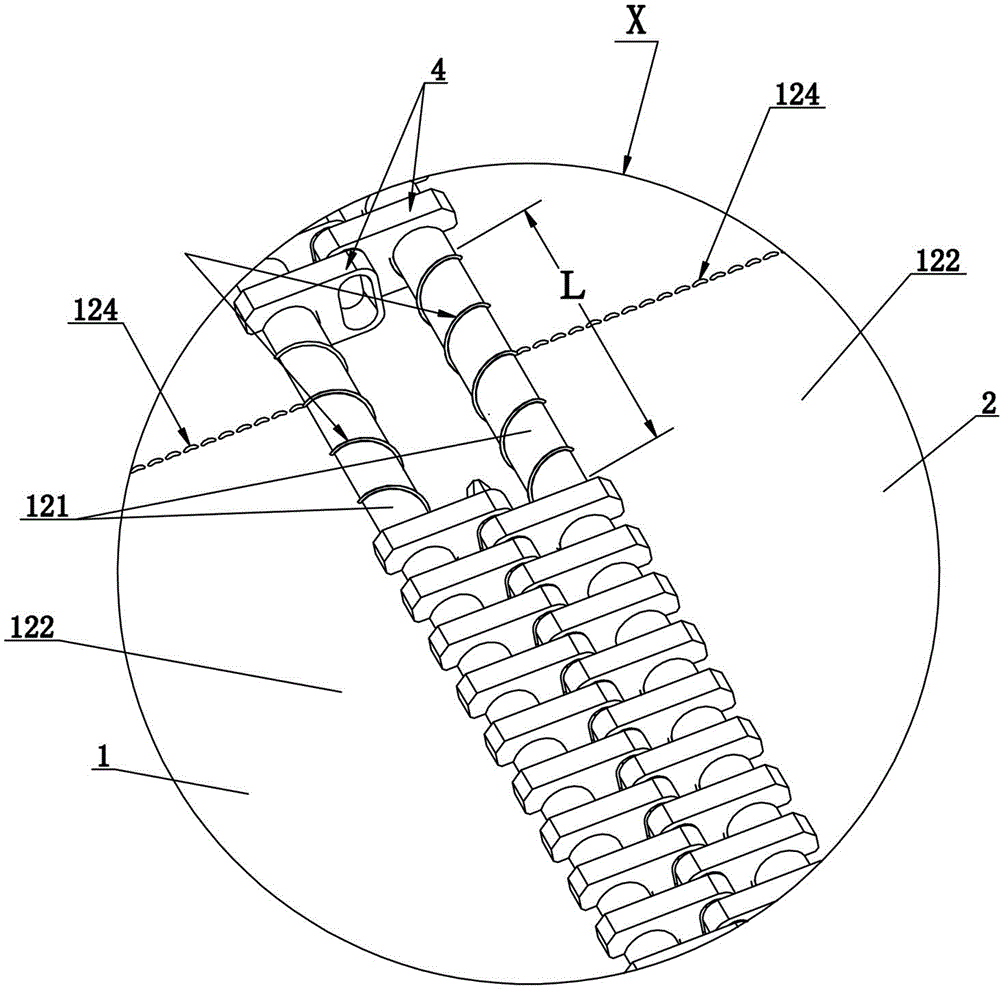
[0025] refer to figure 1 , figure 2 , metal switch zipper, including left cloth belt 1, right cloth belt 2 and slider 3, left cloth belt 1, right cloth belt 2 all comprise cloth reinforcement 121 and cloth surface 122 integrally connected, the thickness of this cloth reinforcement 121 is greater than this cloth According to the thickness of the surface 122, metal chain elements 4 are respectively assembled on the cloth bars 121 of the left cloth tape 1 and the right cloth tape 2. There is a first conductive wire 123, which is arranged to extend along the length direction of the fabric tendon 121. In the winding state, the length L of the first conductive wire 123 along the axial direction (such as figure 2 (shown by the mark L in the middle) is not less than 1 cm; the above-mentioned metal chain element 4 is set on the cloth bar 121 so as to clamp the first wire 123; the above-mentioned cloth surface 122 of the left cloth tape 1 and the right cloth tape 2 The second conduc...

Embodiment approach 2

[0033] refer to Figure 4 , the only difference from Embodiment 1 is that the numbers of the first wires 123 and the second wires 124 provided on the left cloth tape 1 and the right cloth tape 2 are different. The left cloth tape 1 and the right cloth tape 2 of this embodiment Five above-mentioned first wires 123 are respectively provided, and five of the first wires 123 are respectively equipped with one above-mentioned second wire 124; certainly, the configuration quantity of the first wire 123 and the second wire 124 can also be adjusted according to actual needs. set up.


PUM


Abstract

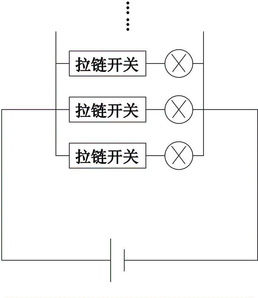
The invention relates to a metal switch zipper and a manufacturing process thereof. The metal switch zipper comprises a left cloth belt, a right cloth belt and a zipper slider, and is characterized in that cloth bars of the left and right cloth belts are respectively and spirally wound with first guide lines; second guide lines are respectively sewn on cloth surfaces of the left and right cloth belts along the width direction of the cloth surfaces by a sewing machine, one end of each second guide line is connected with the corresponding first guide line in series and the other end of each second guide line is connected with a power supply load device; metal zipper teeth are respectively assembled on the left cloth belt and the right cloth belt by a tooth implanting machine; and then the left cloth belt and the right cloth belt are made into a finished zipper product. The metal switch zipper can be taken as one or more switches in a circuit; the guide lines of the zipper are more reasonable in arrangement and can be firmly and stably arranged on the cloth belts without high possibility of falling and twisting, so that the service life of the metal switch zipper is long; and the quantity of circuit switches and the production cost are reduced and the production process is simplified.

Description

technical field [0001] The invention relates to a metal zipper and its production process, in particular to a metal switch zipper and its production process. Background technique [0002] Zippers generally play a sealing role in daily life, and are mostly used in clothing. At present, there are some non-mainstream clothing with electronic components such as light emitting and sounding on the market. Their circuit control is to design a separate circuit, and each closed circuit needs to add an independent switch, which results in the switch and other accessories on the clothing. Too many, the production cost is higher; In addition, the opening or closing of each circuit of the existing non-mainstream clothing needs to be completed manually, and the user needs to complete the operation of opening or closing the circuit when putting it on or taking it off. trouble. [0003] The Chinese utility model patent with the patent number "ZL201220030589.6" discloses an anti-theft zipp...

Claims


Application Information

Patent Timeline
Patent Type & Authority Patents(China)
IPC IPC(8): A44B19/24A44B19/42
Inventor 石胡兵张田李鹏辉刘年喜
Owner FUJIAN SBS ZIPPER SCI & TECH CO LTD
Learn More