Display device and method for producing same

A display device and auxiliary film technology, which is applied in the manufacture of alternating current plasma display panels, discharge tube fluorescent screens, discharge tubes/lamps, etc., to achieve the effects of shortening discharge time lag, increasing secondary electron emission, and reducing costs

Inactive Publication Date: 2013-07-03
TOPPAN PRINTING CO LTD
View PDF5 Cites 1 Cited by
  • Summary
  • Abstract
  • Description
  • Claims
  • Application Information

AI Technical Summary

Problems solved by technology

[0012] (2) As the size of the display screen increases, it is difficult to obtain uniform discharge characteristics over the entire length of the plasma tube extended to more than 1 meter

Method used


Image

  • Display device and method for producing same
  • Display device and method for producing same
  • Display device and method for producing same

Examples


Embodiment approach 1

[0050]

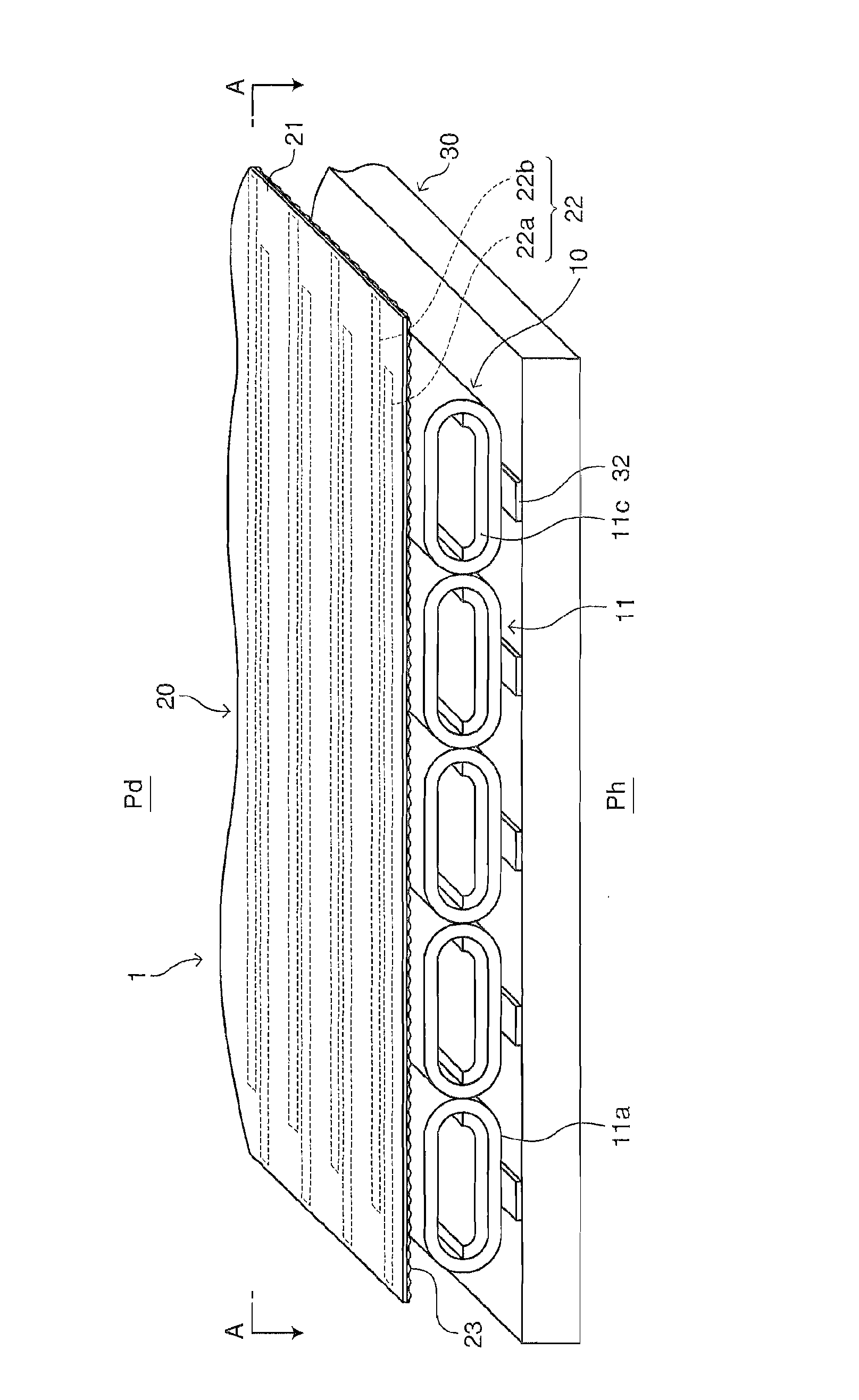
[0051] Such as figure 1 and 2 As shown, the display device 1 of Embodiment 1 includes a plasma tube array 10 , a display electrode sheet 20 and an address electrode sheet 30 . In the display device 1, the display electrode pad 20 is on the front side, that is, the display side Pd, and the address electrode pad 30 is on the back side, that is, the non-display side Pn opposite to the display side Pd. The display device 1 is called a plasma tube array (PTA) type display device.

[0052] The plasma tube array 10 includes a plurality of plasma tubes 11 arranged in parallel.

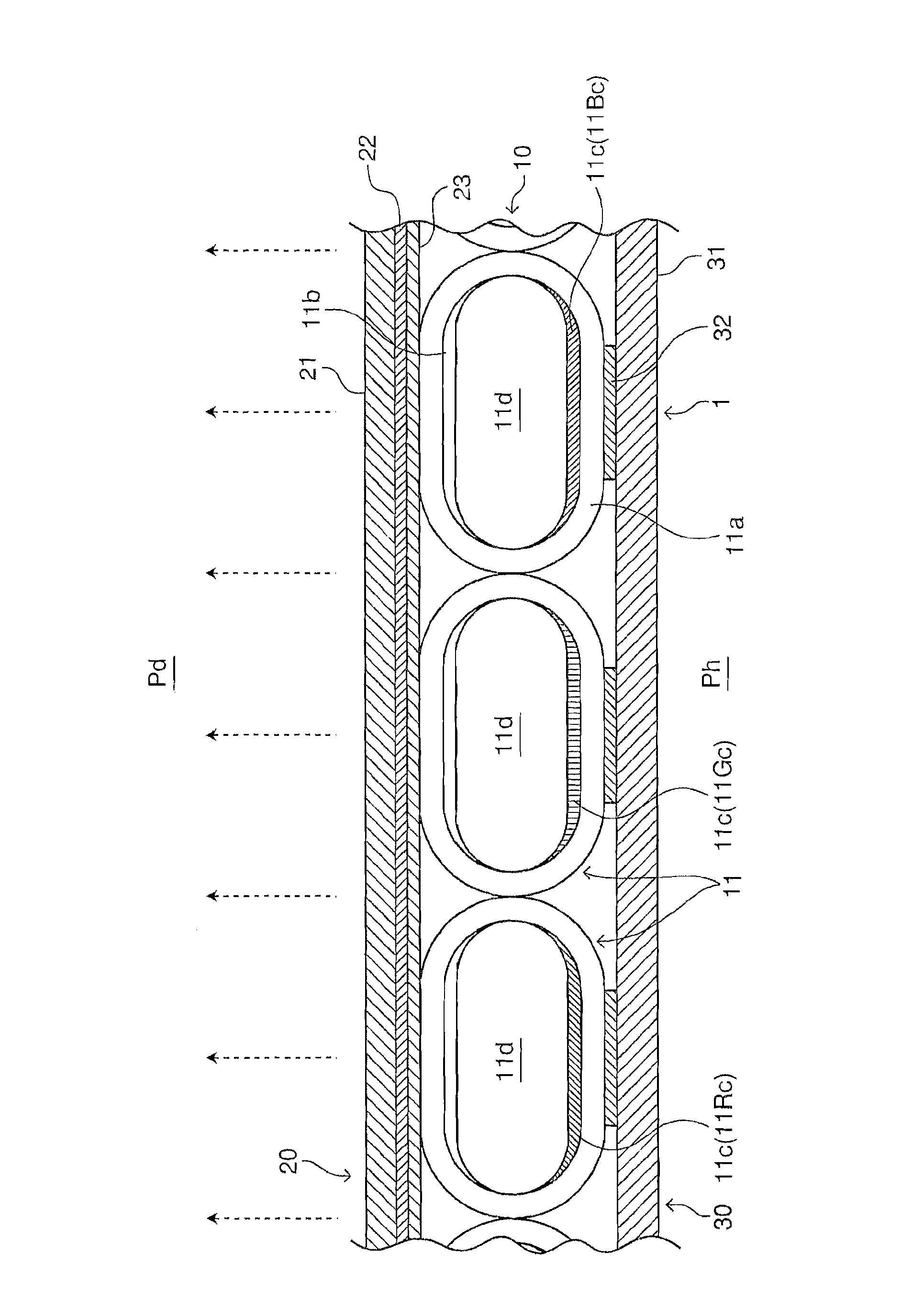
[0053] Each plasma tube 11 has a flat glass tube 11a sealed at both ends, a discharge assisting film 11b provided on the inner surface of the glass tube 11a, and a fluorescent film provided on the inner surface of the glass tube 11a in a region on the back side, that is, on the non-display surface side. 11c and the discharge gas 11d enclosed in the glass tube 11a. Examples of the discharge gas 1...

Embodiment approach 2

[0095] Figure 6 A sectional view illustrating Embodiment 2 of the display device of the present invention. Figure 7 A sectional view for explaining the improvement of the plasma tube in the display device of the second embodiment. Figure 6 and 7 in, with Figures 1 to 5 Components that are the same as those shown are denoted by the same reference symbols. According to the present Embodiment 2, it becomes possible to provide a PTA type display device with high resolution.

[0096]In the plasma tube array 110 in the display device 101 of Embodiment 2, the plasma tubes 111 (flat tubes) are arranged so that the cross section of each plasma tube is long in the vertical direction, and each long diameter is perpendicular to the display electrode sheet 20 and perpendicular to the addressing line. electrode sheet 30. In this case, a discharge assisting film 11b having a relatively large thickness is formed on the curved inner surface of each glass tube 11a on the display surfac...

Embodiment 1

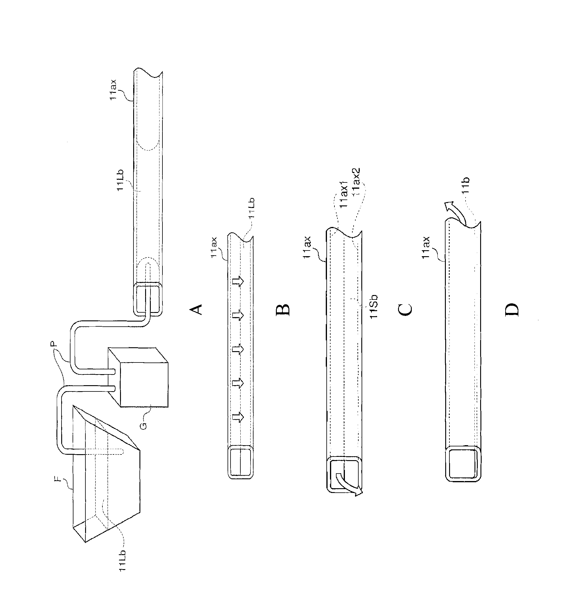
[0099] Plasma tubes each comprising a discharge assisting film and a phosphor film supported by a support and filled with a discharge gas were prepared as follows (see Figure 5 (B)).

[0100] First, 15% by weight of magnesium acetate tetrahydrate, 10% by weight of pure water and 20% by weight of polyoxyethylene alkyl ether are mixed with an alcohol mixture of 25% by weight of ethanol, 10% by weight of ethylene glycol and 20% by weight of glycerin, thereby A material solution for forming a discharge assisting film (for forming a surface layer) is given.

[0101] Next, a glass tube having a flat oval cross-section having a length of 1 m and a major diameter of 1 mm and a minor diameter of 0.5 mm was filled with the material liquid for discharge assisting film formation. A set of 200 glass tubes thus filled with the material liquid was placed in the holder, and four holders were placed radially on the turntable of the rotator. Thereafter, the glass tube was allowed to stand fo...


PUM


Abstract

The invention discloses a display device and a method for producing the same. The display device includes a plasma tube array including a plurality of plasma tubes arranged in parallel; a plurality of display electrodes provided on a front side of the plasma tube array so as to be extended perpendicularly to a longitudinal direction of the plasma tubes; and a plurality of address electrodes provided on a rear side of the plasma tube array so that each address electrode is extended along each plasma tube longitudinally; each plasma tube having a tube, a discharge assisting film having a thickness different from part to part, and a phosphor film, wherein the discharge assisting film is provided on an inner surface of each tube, the thickness of the discharge assisting film is larger at the front side than at the rear side, and the phosphor film is formed on the discharge assisting film at the rear side.

Description

technical field [0001] The present invention relates to display devices. More specifically, the present invention relates to a plasma tube array type display device including a plurality of light-emitting tubes arranged in parallel, each of which is provided with a discharge assisting film (discharge assisting film) on its inner surface, and a production method thereof. assisting film) and phosphor film (phosphor film) and a thin tube filled with discharge gas. Background technique [0002] Japanese Patent 3895202 (US6,893,677B) discloses a display device known as a display device utilizing a technology called "Plasma Tube Array (PTA)", which can be easily produced in a large screen size. [0003] This conventional display device comprises an array of a plurality of light-emitting tubes arranged in parallel, each made of a thin glass tube with a diameter of 0.5 to 5 mm. The glass thin tube is provided with a discharge auxiliary film and a phosphor on the inner surface and ...

Claims


Application Information

Patent Timeline
Patent Type & Authority Applications(China)
IPC IPC(8): H01J11/18H01J1/70H01J9/20
CPCH01J9/02H01J11/18H01J11/40H01J17/49H01J9/20
Inventor 郭滨刚山崎洋介小迫照和
Owner TOPPAN PRINTING CO LTD
Why Eureka
Try Eureka