
Separation process

A one-part, caustic lye technology, applied in the new separation field, which can solve the problem of long residence time affecting the economics of caustic lye treatment methods

Active Publication Date: 2013-07-03
MERICHEM CO
View PDF11 Cites 2 Cited by
  • Summary
  • Abstract
  • Description
  • Claims
  • Application Information

AI Technical Summary

Problems solved by technology

These long residence times adversely affect the economics of the caustic treatment process
In addition, prior art gravity settlers are relatively bulky pieces of equipment

Method used


Image

  • Separation process
  • Separation process
  • Separation process

Examples


Embodiment

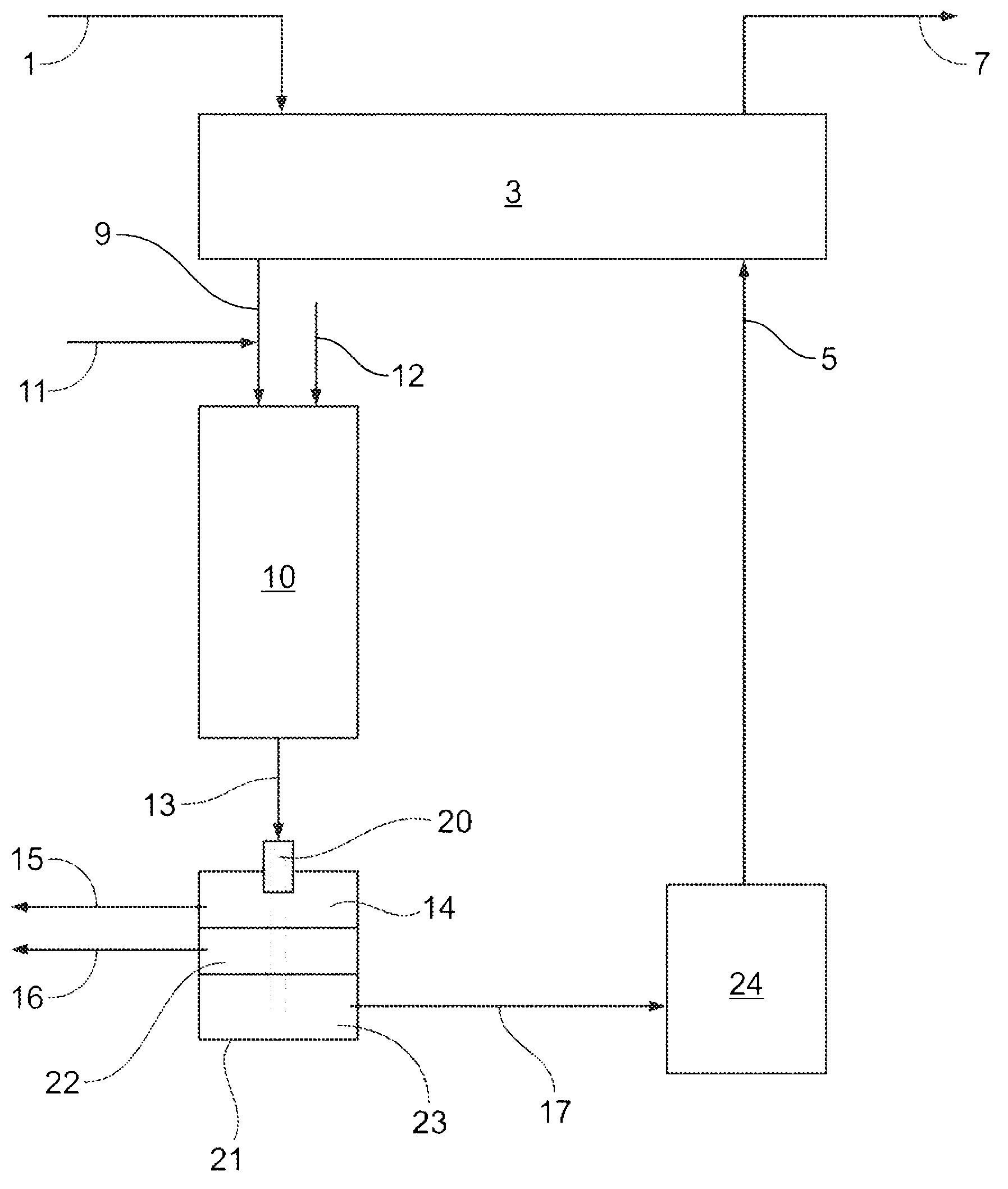
[0036] To illustrate the surprising and unexpected performance of the present invention, laboratory tests were performed to compare a conventional gravity settler (CGS) and the high surface area fiber separator of the present invention. A rich caustic solution of ethanethiol containing about 7000 ppm sulfur was oxidized using a 1-inch diameter oxidizer loaded with ARI-120L solid catalyst at a temperature of about 125°F, 4.0 LHSV and 25 psig back pressure, to 99+% conversion level. Air is injected at about 300ml / min. In a separate test, kerosene was injected into the oxidizer at a rate of about 1.5 ml / min.

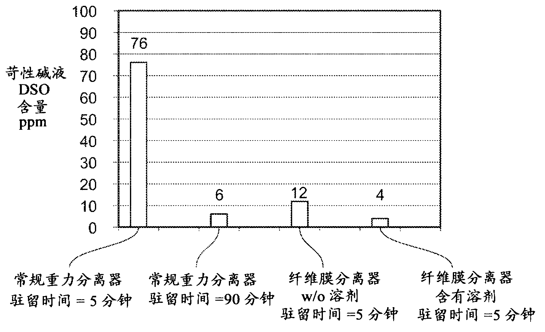
[0037] The effluent from the oxidizer containing about 7000 ppm DSO sulfur as diethyl disulfide was first fed to a 3-inch diameter CGS and gravity settled. After 5 and 90 minutes of residence time, the DSO levels in the caustic dropped to about 76 and 6 ppm, respectively ( figure 2 ).

[0038] Then use FIBER The separator replaces the CGS, and the fibers provide an e...


PUM


Abstract

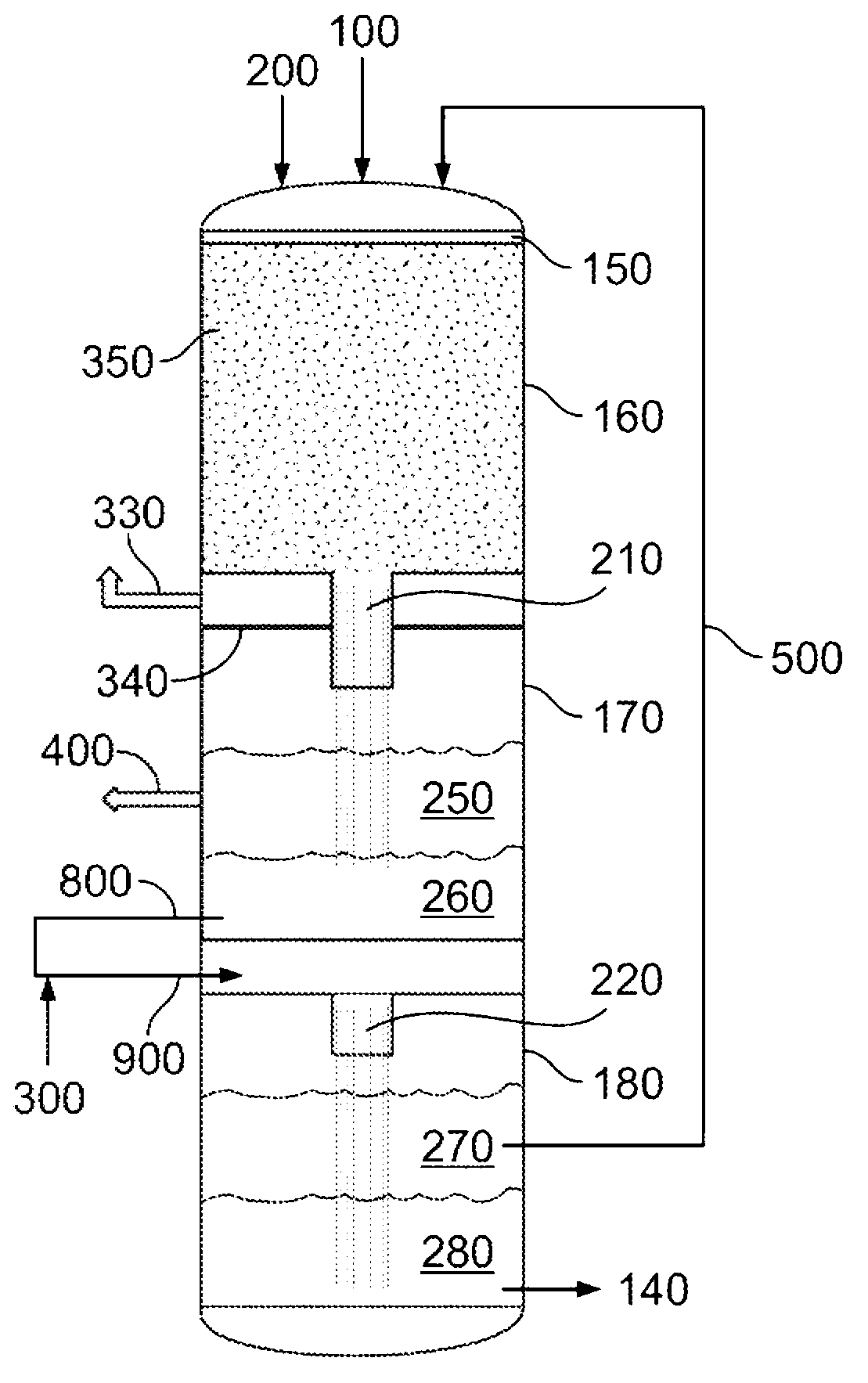
A separation process for separating two or more immiscible liquids using contactors utilizing high surface area vertical hanging fibers is disclosed. This separation process is especially useful in the separation of disulfide oil formed during the oxidation of spent caustic solution that was used to remove sulfur contaminates from light hydrocarbons.

Description

[0001] Cross References to Related Applications [0002] This application claims the benefit of US Patent Application 12 / 849,408, filed August 3, 2010, which is hereby incorporated by reference in its entirety. technical field [0003] The present invention generally relates to new separation techniques for rapid separation of two immiscible liquids using the high surface area and coalescing properties of high surface area vertical hanging fibers. A particular application of the present invention relates to an improved separation process in a single vessel in which disulfides and caustic solutions produced during the removal of sulfur and other contaminants from hydrocarbons including liquefied petroleum gas ("LPG") The mixture is separated into an aqueous caustic stream for recycle and a disulfide-containing organic stream. The present invention significantly reduces separation dwell time, thereby reducing equipment costs and improving the overall efficiency of the process. ...

Claims


Application Information

Patent Timeline
Patent Type & Authority Applications(China)
IPC IPC(8): B01D11/04B01D17/04C10G27/04C10G33/06
CPCB01D11/0453B01D17/045C10G27/04C10G33/06C10G2300/1037C10G2300/1081C10G2300/202C10G2300/4081C10G2300/44B01D11/0492B01D17/02B01D17/10
Inventor 张铁军V.K.特纳
Owner MERICHEM CO
Learn More