
Side column type laundry dryer

A dryer and side column technology, which is applied in the field of side column dryers, can solve the problems of different materials and colors, inconsistent shapes, and poor visual aesthetics, so as to achieve a beautiful appearance and a more beautiful appearance. Uniform, concise intensity effect

Active Publication Date: 2013-07-10
NINGBO JIMU ELECTRICAL APPLIANCE
View PDF7 Cites 1 Cited by
  • Summary
  • Abstract
  • Description
  • Claims
  • Application Information

AI Technical Summary

Problems solved by technology

[0002] The applicant applied on May 21, 2011 for the integrated drying and hanging machine with application number 201110147466.0, the drying machine with application number 201110147452.9, the integrated drying and ironing machine with application number 201110147430.2, and the application on June 29, 2011 The application number is 201110142427.4 for an integrated drying and ironing machine. The four patents of this application disclose a drying structure in which the cloth cover is located on one side of the column. The fixed parts and connecting joints are generally made of plastic materials, and the telescopic rods are generally made of metal materials, with different materials and colors; on the other hand, the fixed parts of the drying rack parts, the fixed parts of the column and the base, and the fixed parts of the air outlet tray , columns, the short columns that make up the entire column, and the connection joints between each short column have different material forms, so when viewed from the other side of the drying area, the fixed parts of the column and the drying rack parts, The fixed part of the column and the base, and the fixed part of the air outlet plate are all exposed outside, which cannot be unified in form, and the visual aesthetics is poor
In addition, although the structure of the fixing device is disclosed, it does not clarify the upright column in the section between the fixing part of the drying rack part and the fixing part of the air outlet pan, or the upright column in the section between the fixing part of the drying rack part and the fixing part of the air outlet pan. A technical solution with unified shape and beautiful appearance of multiple parts such as the connecting joint between the short column and the short column

Method used


Image

  • Side column type laundry dryer
  • Side column type laundry dryer
  • Side column type laundry dryer

Examples


no. 1 example

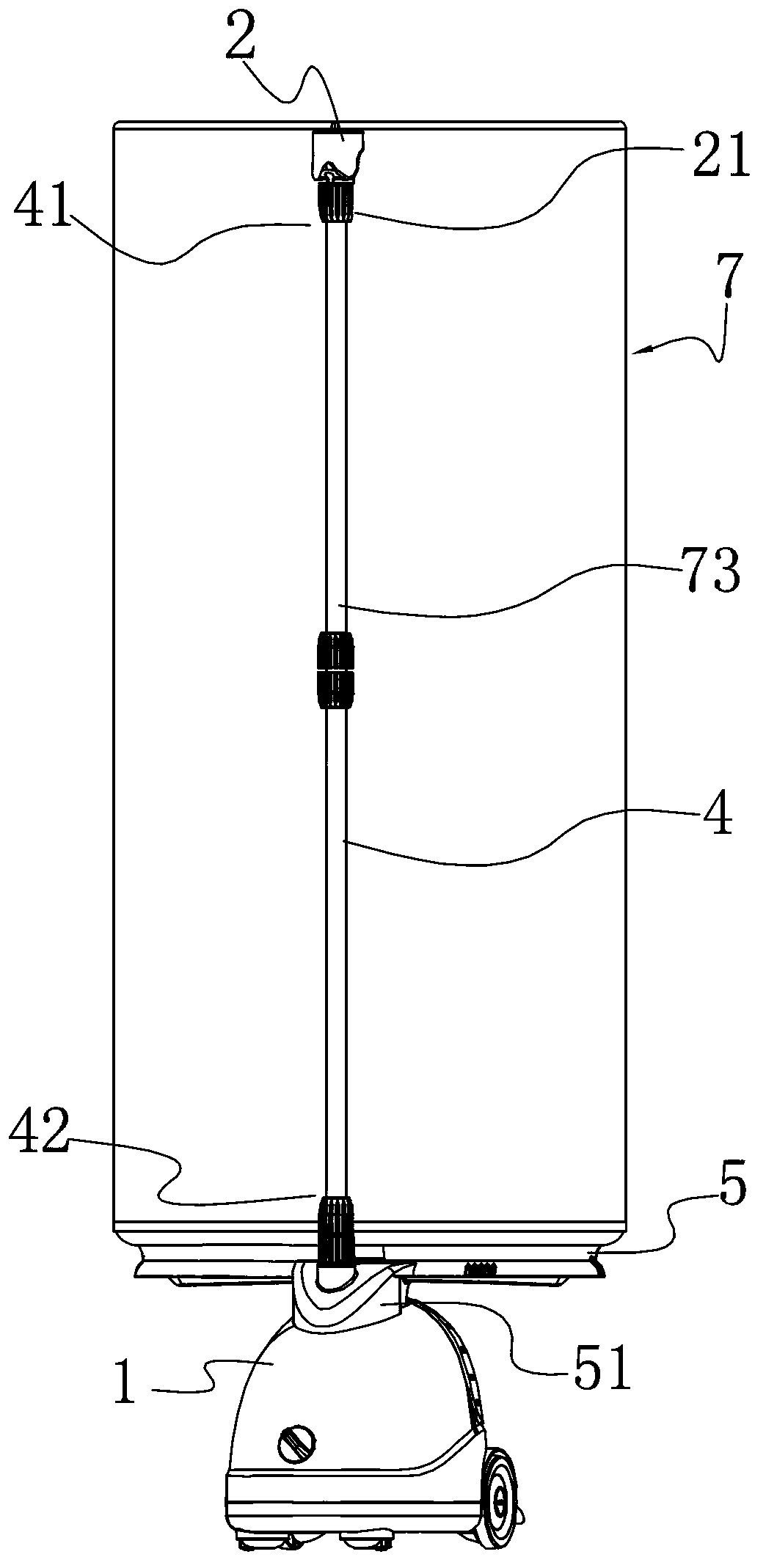
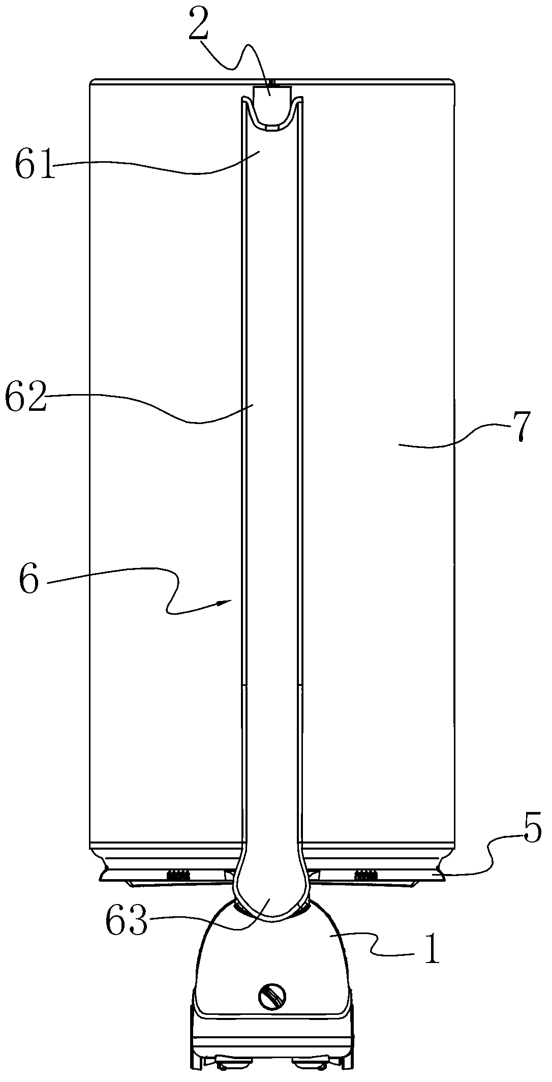
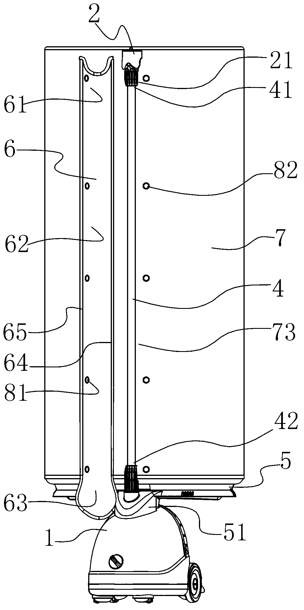
[0027] Such as Figure 1A , 1B As shown, this clothes dryer is assembled by frame part and cloth cover 7. The frame part includes a base 1, a column 4 whose lower end 42 is fixed on the base, a drying rack component 2 fixed on the upper end 41 of the column through the drying rack component fixing part 21, and an air outlet plate fixed on the lower end of the column through the air outlet disc fixing part 51 5; The upper end surface of the cloth cover 7 is supported on the drying frame part 2, and the lower end surface is closed on the air outlet tray 5. After packing together like this, the column 4 of section between the fixed part 21 of the drying rack part and the fixed part 51 of the air outlet tray 5 is exposed outside the cloth cover 7, and one side of the column 4 is close to the cloth cover 7 back side. The upper section 61 of a cover sheet 6 covers the fixing part 21 of the drying rack part, the middle section 62 covers the column 4 of the section between the fixing...

no. 2 example

[0033] Such as image 3 As shown, different from the above-mentioned first embodiment, the cover sheet 6 includes an outer ring portion 66 and an inner ring portion 67 extending longitudinally, the inner ring portion 67 is located in the middle, and the outer ring portion 66 is located in the inner ring part 67 on both sides. The longitudinal strip-shaped inner ring portion 66 extends from the upper section 61 to the lower section 63 through the middle section 62 , but does not extend to the bottom end of the cover sheet 6 . That is to say, the cover sheet 6 is divided into three strips in the longitudinal direction except the bottom end, the middle one is the inner ring portion 66 , and the other two on both sides are the outer ring portion 67 .

[0034] The advantage of such a structure is that the outer ring portion 67 can use a fabric that is more conducive to the fixing of the female button 81 than the inner ring portion 66. For example, the density of the fabric is rela...

no. 3 example

[0037] The difference from the second embodiment is that, optionally, all or part of the material of the cover sheet 6 is made of see-through material, so as to form a see-through window. Such as Figure 4A As shown, the inner ring portion 66 of the cover sheet 6 adopts a see-through material, and the inner ring portion 66 forms a see-through window 68, through which the operator can clearly know the specific positions of each component, which is beneficial to the oven through the cover sheet 6. The operation inside the clothes machine is of course also conducive to quickly and accurately opening the snap button at the position to be operated, so as to operate the inside. For example, when the column 4 is composed of multiple stretchable short pipes, the operator can clearly see the fixed connections between the short pipes at a glance, and can quickly and conveniently operate the corresponding fixed connections to adjust the height of the dryer. So the role of the perspectiv...


PUM


Abstract

A side column type laundry dryer comprises a base, an upright, a cloth cover positioned on one side of the upright, a drying frame part fixing portion positioned at the upper end of the upright, and an air outgoing disc fixing portion positioned at the lower end of the upright. The side column type laundry dryer is characterized in that an elongated cover piece longitudinally extending, the upper section of the cover piece covers the drying frame part fixing portion, the middle section of the cover piece covers the part of the upright, between the drying frame part fixing portion and the air outgoing disc fixing portion, the lower section of the cover piece covers the air outgoing disc fixing portion, and two lateral edges in the longitudinal direction of part of the cover piece are connected on the bonding sides of the cloth cover and the upright respectively. The cover piece is arranged on the outer side of the upright, so that the side column type laundry dryer is uniform in overall appearance posture, good in visual effect and higher in strength while attractiveness and compactness in appearance is guaranteed.

Description

technical field [0001] The invention relates to a clothes dryer, in particular to a side column dryer. Background technique [0002] The applicant applied on May 21, 2011 for the integrated drying and hanging machine with application number 201110147466.0, the drying machine with application number 201110147452.9, the integrated drying and ironing machine with application number 201110147430.2, and the application on June 29, 2011 The application number is 201110142427.4 for an integrated drying and ironing machine. The four patents of this application disclose a drying structure in which the cloth cover is located on one side of the column. The fixed parts and connecting joints are generally made of plastic materials, and the telescopic rods are generally made of metal materials, with different materials and colors; on the other hand, the fixed parts of the drying rack parts, the fixed parts of the column and the base, and the fixed parts of the air outlet tray , columns, ...

Claims


Application Information

Patent Timeline
Patent Type & Authority Applications(China)
IPC IPC(8): D06F58/20
Inventor 胡杰波
Owner NINGBO JIMU ELECTRICAL APPLIANCE
Learn More