Installation type templates, installation type template group and set of installation type template devices

A formwork group and formwork technology, applied in construction, infrastructure engineering, etc., can solve problems such as affecting the pouring effect, potential safety hazards, and dimensional disturbances.

Active Publication Date: 2013-07-10
STATE GRID CORP OF CHINA +1
6 Cites 4 Cited by

AI-Extracted Technical Summary

Problems solved by technology

At present, in the traditional construction, the support steel pipe 62 is used to cooperate with the bamboo glue formwork to complete the support construction formwork and the construction operation platform 61. When the span of the foundation pit 64 is too large, in order to realize the stability of the steel pipe frame and solve the construction formwork and construction operation The support problem of the platform 61 requires a large number of supporting steel pipes 62 to set up dense scaffolding for support and clamping. At this time, the supporting steel pipes 62 need to be inserted into the foundation floor 65, which will cause some artificial damage to the foundation body structure, and the pouring process supports the steel pipes 62 Easy to slip
[0005] At the same time, when the cons...

Method used

(5) Bolts and fixtures 25 are used between the mounting formwork, that is, the angle steel connects the rest of the mounting formwork to the design elevation from bottom to top, and attention is paid to using the bolt holes 11 of the mounting formwork and the angle steel adjustment in the installation process The cross-sectional size of the installed formwork makes the joints between the installed formwork tight and the surface smooth;
Please refer to Fig. 3, Fig. 3 is the structural representation that the installation type formwork group provided by the embodiment of the present invention cooperates with the ground fixed guy wire of the formwork group, specifically, above-mentioned installation type formwork group 2 also includes the formwork group ground fixing One end of the stay wire 31 and the fixed formwork group ground The stay wire 31 is fixedly connected to the ground 32 , and the other end is fixedly connected to the installed formwork group 2 . The ground 32 is preferably the ground outside the pit mouth of the foundation, and the position of the formwork system can be controlled more accurately by adopting the control method of the outer stay wire.
The installation formwork that the embodiment of the present invention provides adopts the form that glass fiber reinforced plastic panel and steel-wood structure are combined, has the characteristics of large cross-section, light weight, stable structure, convenient installation, and molding is accurate and can not occur slurry leakage phenomenon, After pouring, the concrete surface is smooth, the ridges and corners are straight, and there is no honeycomb or pitting.
[0036] The main frame 12 has a front surface that can be used to attach and fix the panel 14, and also has four sides, and these four sides are provided with bolt holes 11 to facilitate fixed connection with bolts. So specifically, the main frame 12 can be welded into a square or a rectangle by four angle irons, and the angle irons are composed of two angle wings arranged at 90°. Among the four angle irons, each angle iron forms a corner Wings, the outer ...

Abstract

The invention discloses installation type templates which are used for foundation construction. Every installation type template comprises a main frame which comprises a front surface, a rear surface and four lateral sides, wherein a face plate is arranged on the front surface and the four lateral sides are provided with bolt holes. When installation type templates are used, the front surface faces inward, namely the face plate faces inward, four installation type templates are surrounded into a circle through bolts and sequentially connected with each other to form into vertical space to build a first subtemplate system, and a second subtemplate system is built in the same way. The first subtemplate system is fixedly connected with the second subtemplate system through the bolts on the bases of the first subtemplate system to build a template system with the required height. The installation type templates have the advantages of needing no supporting steel pipe, causing no damage to a basic body structure, being capable of being separated from a construction platform and enabling the template system to be not affected by construction loads, such as slurry downward, vibration and staff operation which are performed on the construction platform due to the fact that the template system is built in an assembling way.

Application Domain

Foundation engineering

Technology Topic

EngineeringSurface plate +2

Image

  • Installation type templates, installation type template group and set of installation type template devices
  • Installation type templates, installation type template group and set of installation type template devices
  • Installation type templates, installation type template group and set of installation type template devices

Examples

  • Experimental program(1)

Example Embodiment

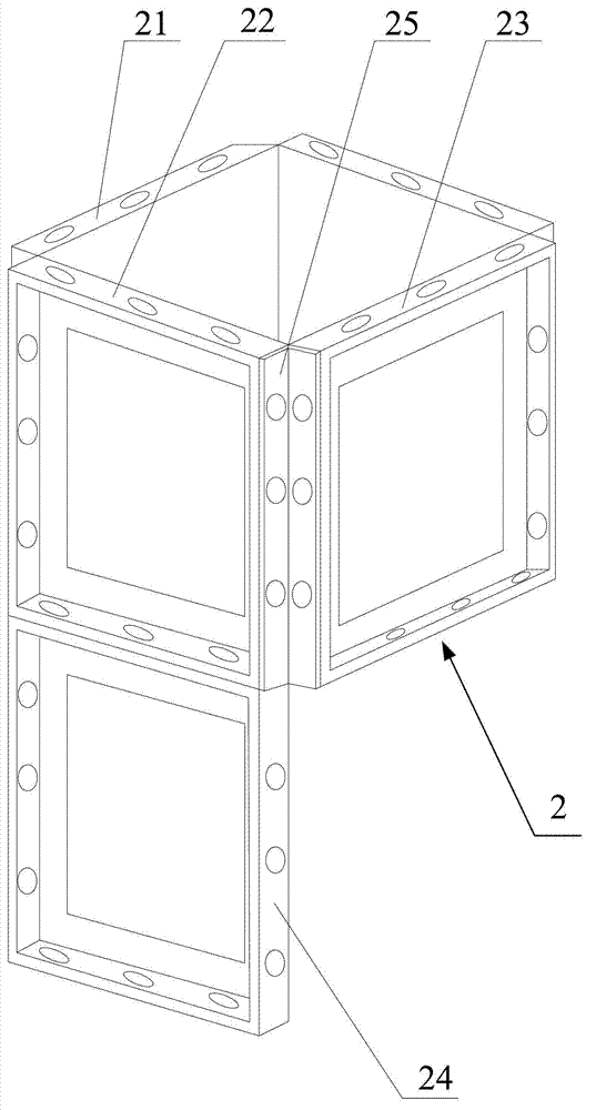
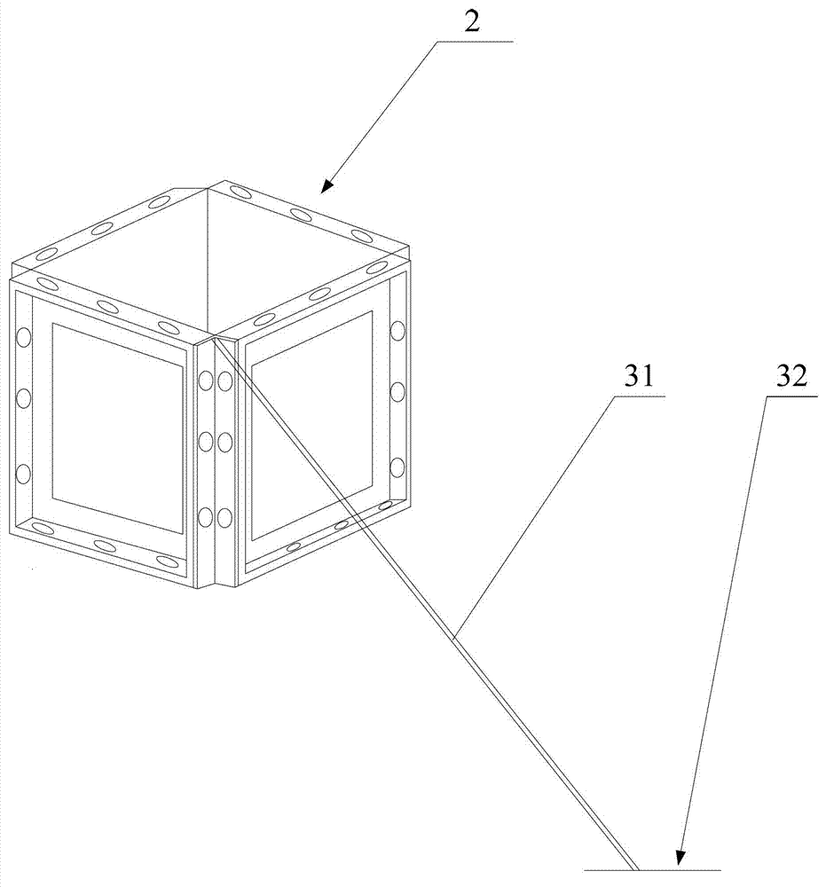
[0030] The core of the present invention is to provide an installation formwork to realize the separation of the formwork system and the construction operation platform; another core of the present invention is to provide an installation formwork group and a complete set of installation formwork devices.
[0031] In order to enable those skilled in the art to better understand the solution of the present invention, the present invention will be further described in detail below with reference to the accompanying drawings and specific embodiments.
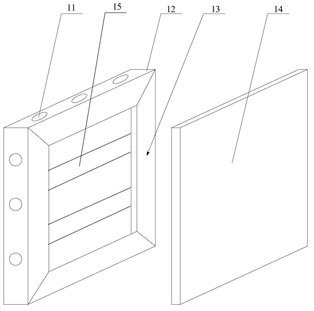
[0032] Please refer to figure 1 , figure 1 It is a schematic diagram of the exploded structure of the installation template provided by the embodiment of the present invention.
[0033] The installation formwork provided by the embodiment of the present invention is used for foundation construction and includes a main frame 12, which includes a front surface, a back surface, and four side surfaces, wherein a panel 14 is provided on the front side, and bolts are provided on all four sides Hole 11.
[0034] When in use, the front face is facing inward, that is, the panel 14 is facing inward, and then the four mounting templates are surrounded by bolts and connected in turn to form a three-dimensional space. The first sub-formwork system is built, and then the same is completed. The second sub-formwork system, on the basis of the first sub-formwork system, is fixed in height with the second sub-formwork system through bolts, until the final formwork system that needs the height is built, here you can refer to it Image 6 , Image 6 This is a schematic structural diagram of a complete installation formwork device provided by an embodiment of the present invention. The installation formwork provided by the present invention is assembled to build a formwork system without supporting steel pipes, causing no damage to the basic body structure, and being able to completely The formwork system is separated from the construction operation platform 61, and the formwork system will not be affected by construction loads such as sizing, vibrating, and personnel operations on the construction operation platform 61. Such as Image 6 , The connection parts of the construction template and the construction operation platform 61 are independent of each other and do not interfere with each other, and the construction operation platform 61 only bears the construction load.
[0035] Of course, you can also directly install the first installation template, the second installation template, the third installation template and the fourth installation template in the second sub template system directly on the basis of the first sub template system. The template, and finally the second sub-template system is formed on the basis of the first sub-template system. The present invention does not limit the specific installation method of the installation-type template.
[0036] The main frame 12 has a front surface that can be used to attach and fix the panel 14 and also has four sides. The four sides are provided with bolt holes 11 to facilitate fixing and connection with bolts. Specifically, the main frame 12 can be formed by welding four angle irons into a square or rectangle. The angle irons are composed of two angle wings set at 90°. Among the four angle irons, each angle iron has a corner. The outer sides of the four corner wings together form a panel installation plane 13 for installing the panel 14. The other corner wing is provided with bolt holes, which are connected by bolts, so that the joints between the mounting templates are tight.
[0037] At the same time, the conventional formwork in the prior art has extensive processes, complicated procedures, cannot achieve standardized operations, and has low construction efficiency. However, the installation formwork provided by the embodiments of the present invention can be assembled in a standardized manner, and the number of equipment and tools required for construction is small. , Can form a fixed operating procedure, quantify the number of construction personnel, and achieve standardized operations. And the construction operation is simple, the construction process is not complicated, the construction period is effectively shortened, the economic effect is very obvious, and it has promotion value, so that the flexible large slab foundation construction can be standardized and standardized.
[0038] Specifically, the panel 14 is a glass steel panel. At present, the bamboo glue formwork used in the prior art absorbs water and expands after being used for a certain period of time, causing unevenness and damage to the formwork, which affects the final pouring quality and has a relatively large safety hazard. The FRP panel is selected as the panel 14. Because the surface of the FRP panel is flat, high strength, non-absorbent, and non-deformed, the reuse rate of the formwork is increased, and the smoothness and flatness of the surface after concrete pouring is also improved.
[0039] In addition, the bamboo glue formwork used in the prior art will cause the concrete column ridgeline to be not straight, have burrs, corners and corners are damaged or defective, and the concrete surface formwork joints are obvious, and some of the concrete leakage phenomenon is provided by the embodiment of the present invention The installation formwork utilizes the strength and smoothness of the glass fiber reinforced plastic panel to improve the reuse rate and the smoothness of the concrete surface after pouring, which effectively avoids various problems in the prior art mentioned above.
[0040] Specifically, the main frame 12 is a steel-wood structure. Steel-wood structure is a hybrid structure that combines modern steel structure and traditional wooden structure 15. Among them, the columns, beams and other force-bearing components adopt the form of steel structure, and the outsourcing adopts the wooden structure15. At present, the bamboo glue formwork used in the prior art has poor structural stability and loose joints. If the steel structure is simply used, its own weight is relatively high. Heavy and inconvenient to install. Choose to use steel-wood structure, which has light weight, high strength, low safety risk, simple assembly method, accurate positioning, tight joints, and no leakage. The installation and construction efficiency is high, it can be reused many times, and the application range is wide. In addition, the steel-wood structure can not only ensure the strength of the installation formwork, but also reduce the weight of the installation formwork, which is convenient for construction and installation.
[0041] The installation formwork provided by the embodiment of the present invention adopts a combination of a glass fiber reinforced plastic panel and a steel-wood structure, and has the characteristics of large cross-section, light weight, stable structure, convenient installation, and accurate molding without slurry leakage, so that it can be poured The surface of the rear concrete is smooth, with straight edges and corners, and no honeycomb or pockmarked surface occurs.
[0042] Please refer to figure 2 , figure 2 It is a schematic diagram of the structure of the installation template group provided by the embodiment of the present invention. The embodiment of the present invention also provides an installation type template group 2, including an installation type template. The installation type template is an installation type template as in any one of the above embodiments. The four sides of the installation type template are the upper side, the lower side, The left side and the right side also include a fixing device 25 for fixedly connecting the left side of the first installation template and the right side of the second installation template, and the lower side of the first installation template and The upper side of the third mounting formwork is fixedly connected with bolts.
[0043] The installation formwork group 2 is equivalent to the above-mentioned first sub-formwork system or the second sub-formwork system. Of course, since three installation forms can form a sub-formwork system to form a three-dimensional space, here it only includes four Take installation template group 2 of two installation templates as an example for description.
[0044] Such as figure 2 , The four installation templates include No. 1 template 21, No. 2 template 22 and No. 3 template 23. First, we use No. 1 template 21 as the second installation template, and No. 2 template 22 as the first installation template. , Then the left side of the second template 22 and the right side of the first template 21 are fixedly connected by the fixing device 23, and then we use the third template 23 as the first installation template, and the second template 22 as the second installation Type template, then the left side of the third template 23 and the right side of the second template 22 are fixedly connected by a fixing device 23, and then analogously to form an installation template group 2.
[0045] Then there is the superposition of the height of the two installation template groups 2, we add another installation template, called the fourth template 24, we use the second template 22 as the first installation template, and the second template 22 as the first If there are three installation templates, the lower side of the second template 22 and the upper side of the fourth template 24 are fixedly connected by bolts, and so on, and finally a template system conforming to the height is formed.
[0046] Specifically, the fixing device 25 is an angle steel, and two corner wings of the fixing device 25 are provided with bolt holes. From figure 2 It can be seen that when the two installed formwork are fixedly connected, their sides form a right-angled space together, so the space is just filled with angle steel. The bolt holes on the two angle wings of the angle steel and the two installed formwork sides The bolt holes 11 are respectively aligned and then fixed with bolts.
[0047] In order to achieve a better fixing effect, the entire formwork system can only use four very long angle steels. Take the second formwork 22, the third formwork 23 and the fourth formwork 24 as examples. The angles are used in the second formwork 22 and the third formwork. While the 23 is fixedly connected together, the No. 3 template 23 and the No. 4 template 24 can also be fixedly connected together, thereby enhancing the fixing effect.
[0048] Please refer to Figure 4 , Figure 4 It is a schematic structural diagram of the installation type template set provided by the embodiment of the present invention and the anti-prism fixing device used together. Specifically, the above-mentioned installation-type template group 2 further includes an anti-prismatic fixing device 4 that fixedly connects the upper side of the first installation-type template and the upper side of the second installation-type template. We take No. 2 template 22 and No. 3 template 23 as examples. No. 2 template 22 is used as the first installation template, and No. 3 template 23 is used as the second installation template. The anti-prismatic fixing device 4 can be rod-shaped or plate. Here we take the angle steel as an example. When installing the angle steel, both ends of the angle steel are provided with bolt holes. We connect the bolt holes at both ends of the angle steel to the bolt holes on the upper side of the No. 2 template 22 and the No. 3 template 23 respectively. Align the bolt holes on the upper side of the assembly and fix the connection with bolts to prevent prismatic deformation of No. 2 template 22 and No. 3 template 23. When the installation template group 2 is composed of four installation templates, the two adjacent ones are installed An anti-prismatic fixing device 4 can be provided on the upper side of the type template. Generally, four anti-prismatic fixing devices 4 can be provided.
[0049] Specifically, the above-mentioned installation template group 2 further includes an inner drawing screw 51 for fixing and tightening any two installation templates. In the prior art, when the cross-section of the project column is large, it is very easy to cause the bulging of the construction template during the construction process. Generally, the support rod is set up between the pit wall of the foundation pit and the template. However, due to the length of the top support It is longer, so the effect of avoiding the bulge of the template is not obvious, and it will cause confusion in the foundation pit, and the process is not uniform. However, the method of pulling the screw inside can avoid the phenomenon of more and more messy top braces in the foundation pit, making the foundation pit The specifications are neat, concise and clear, and can completely avoid the bulging phenomenon of the foundation column, and can also prevent deformation.
[0050] When setting the inner drawing screw 51, we take the installation template group 2 including four installation templates, and the inner drawing screw 51 is set on the two opposite installation templates as an example. Please refer to Figure 5 , Figure 5 This is a schematic diagram of the structure of the installation template group and the inner drawing screw provided by the embodiment of the present invention. It is assumed that the two installation templates of the four installation templates are the second template 22 and the fifth template 26 respectively. Two vertical support rods 52 are set on the reverse side of the second template 22, and then a fixed plate 53 is clamped horizontally. The fixed plate 53 is fixed with one end of the inner drawing screw 51, and then the other end of the inner drawing screw 51 is installed from After passing through the three-dimensional space formed in the middle of the type template group 2, after reaching and passing through the No. 5 template 26, the inner drawing screw 51 is fixed in the same way as the front No. 2 template 22, and the other end of the inner drawing screw 51 is fixed at night. Thus, the inner drawing of the inner drawing screw 51 is completed, and the second template 22 and the fifth template 26 are tightened to prevent bulging. The inner drawing screw 51 is preferably set from a position 1 meter below the upper side of the mounting template.
[0051] Please refer to image 3 , image 3 It is a schematic diagram of the structure of the installation formwork group and the ground fixing cable of the formwork group provided by the embodiment of the present invention. Specifically, the above-mentioned installation formwork group 2 also includes the ground fixing pulling wire 31 of the formwork group and the ground fixing pulling wire 31 of the formwork group. One end is fixedly connected to the ground 32, and the other end is fixedly connected to the installation formwork group 2. The ground 32 is preferably the ground outside the opening of the foundation pit, and the position of the formwork system can be controlled more accurately by adopting an external cable control method.
[0052] Specifically, the installation template includes a dedicated template and a public template. Since the height of the formwork system ultimately required is determined according to different site conditions, only a single-height installation formwork is not acceptable, but if there are too many heights of installation formwork, it will undoubtedly increase the production cost and use it. It is more troublesome. Therefore, the installation template needs to include special templates and public templates. Among them, the number of public templates is the largest and the most widely used. Use as many public templates as possible, and then use as few special templates as possible. For type and type, the template is divided into series according to the cross-sectional size, such as 1.8m cross-section, 2.0m cross-section, 2.2m cross-section, etc. For example, taking the installation template with a cross-section of 2.0m as an example, we will use the 1.2m height as public The template is used, and the height of 1.0m, 0.8m, 0.6m is used as a special template. In actual use, several installation template groups 2 composed of public templates and one installation template group 2 composed of special templates can be used. Assembled into a formwork system of various heights to adapt to foundation construction.
[0053] Please refer to Image 6 , Image 6 It is a schematic structural diagram of a complete set of installation formwork device provided by an embodiment of the invention. The embodiment of the present invention also provides a complete installation formwork device, including an installation formwork group 2, which is the installation formwork group 2 according to any one of the above embodiments, and further includes a road wood 72, a road wood 72 A steel beam 71 is provided thereon, and the steel beam 71 has a connecting bolt hole for fixing with the bolt hole 11 on the installation template group 2 in the installation template group 2.
[0054] When the complete set of installation template device provided by the embodiment of the present invention is used:
[0055] (1) Set up the facility worker operating platform 61, and use the installation template set 2 provided in the embodiment of the present invention, and the installation template set 2 uses the installation template provided in the embodiment of the present invention, and the installation template includes a special template. And public templates, choose the corresponding types of templates to meet the height requirements of the basic design after matching;
[0056] (2) Set up road wood 72 at the bottom of the foundation pit and complete the leveling;
[0057] (3) Place a steel beam 71 on the rail 72 that has been leveled, and level and level the steel beam 71.
[0058] (4) Connect the two mounting templates through the fixing device 25, that is, angle steel, and align the bolt holes 11 on the lower side of the two mounting templates with the connecting bolt holes on the steel beam 71 and use bolts Fix the connection, and then install the installation formwork on the other two sides to form an installation formwork group 2. After the installation is completed, the installation formwork group 2 is aligned to ensure that the overall position and size of the column formwork system meet the design requirements;
[0059] (5) Bolts and fixing devices 25 are used between the installation templates, that is, the angle steel connects the remaining installation templates to the design elevation from bottom to top. During the installation process, pay attention to using the bolt holes 11 of the installation template and the angle steel to adjust the installation template The size of the cross-section makes the joints between the installed templates tightly and the surface smooth;
[0060] (6) Set the formwork group ground fixing cable 31 for fixing the foundation post. The foundation post is a formwork system composed of the installation formwork group 2. The four corners of the uppermost plane of the foundation post are fixed on the ground with the four corners of the foundation pit. Pull wires 31, the ground fixing wires 31 of the formwork group are fixed by ground anchors. The ground fixing wires 31 of the formwork group are used to adjust the root opening and cross section of the upper plane of the installed formwork. After the adjustment is completed, they are set at the four corners of the uppermost plane of the foundation column. Anti-prismatic fixing device 4;
[0061] (7) Check the dimensions of each part of the foundation column immediately after installation to ensure the installation quality.
[0062] The complete installation formwork device provided by the embodiment of the present invention adopts the steel beam 71 to support the entire foundation column, which has high stability and can more accurately control the position of the formwork system.
[0063] The complete installation formwork device provided by the embodiment of the present invention is suitable for the construction of flexible large slab foundations in 1000kV UHV project construction. Of course, the flexible large slab foundations of ±800 and 750kV line projects can also be used.
[0064] The installation template, installation template group and complete installation template device provided by the present invention have been described in detail above.
[0065] Specific examples are used in this article to illustrate the principle and implementation of the present invention. The description of the above examples is only used to help understand the method and core idea of ​​the present invention. It should be pointed out that for those of ordinary skill in the art, without departing from the principle of the present invention, several improvements and modifications can be made to the present invention, and these improvements and modifications also fall within the protection scope of the claims of the present invention.

PUM

no PUM

Description & Claims & Application Information

We can also present the details of the Description, Claims and Application information to help users get a comprehensive understanding of the technical details of the patent, such as background art, summary of invention, brief description of drawings, description of embodiments, and other original content. On the other hand, users can also determine the specific scope of protection of the technology through the list of claims; as well as understand the changes in the life cycle of the technology with the presentation of the patent timeline. Login to view more.
Why Eureka
Try Eureka