Power gear-shifting speed-change control system

A control system and power shifting technology, which is applied in the field of mechanically controlled power shifting and shifting control systems, can solve the problems of large shifting impact, small transmission torque, and poor performance, and achieve the goal of ensuring output pressure and avoiding impact Effect

Inactive Publication Date: 2013-07-10
JIANGSU LIUGONG MACHINERY
View PDF10 Cites 3 Cited by
  • Summary
  • Abstract
  • Description
  • Claims
  • Application Information

AI Technical Summary

Problems solved by technology

[0002] At present, power shifting is widely used in the transmission system of construction machinery. Basically, hydraulic slide valves are used to control the oil circuit of the gearbox clutch to realize gear shifting. This kind of on-off control of the oil circuit will bring greater Shifting shock, if the shock is too large, it will affect the operating comfort of shifting and the life of parts
In order to solve the impact phenomenon during the shifting process, it is mainly to install a buffer device in the main oil circuit. Before the hydraulic oil enters the clutch of each gear, the oil pressure is buffered to delay the pressure build-up time. Although this solution has played a role to a certain extent The function of buffering, but because it is buffered on the main oil circuit, there is only one buffering time, but in the actual shift process, the transmission torque of the low gear is relatively large, the required gear time is long, and the transmission torque of the high speed gear is small, so The required shifting time is short. If the buffer valve is installed on the main oil circuit to meet the requirements of the long buffering time of the low-speed gear, the "equal gear" phenomenon with slow combination time will appear in the high-speed gear shifting. If it meets the high-speed gear first The requirements of gears will inevitably lead to more severe impact during the shifting process of low-speed gears. Generally, the shifting time of low-speed gears and high-speed gears will be taken into account, which will make the shifting time of low-speed gears shorter than the actual demand, resulting in the shifting process. There is a more obvious sense of impact; the shifting time of the high-speed gear is longer than the actual demand, resulting in the phenomenon that the shifting has been switched, but the clutch is lagging behind. Difference

Method used


Image

  • Power gear-shifting speed-change control system
  • Power gear-shifting speed-change control system
  • Power gear-shifting speed-change control system

Examples


Embodiment Construction

[0013] The present invention will be further described below in conjunction with drawings and embodiments.

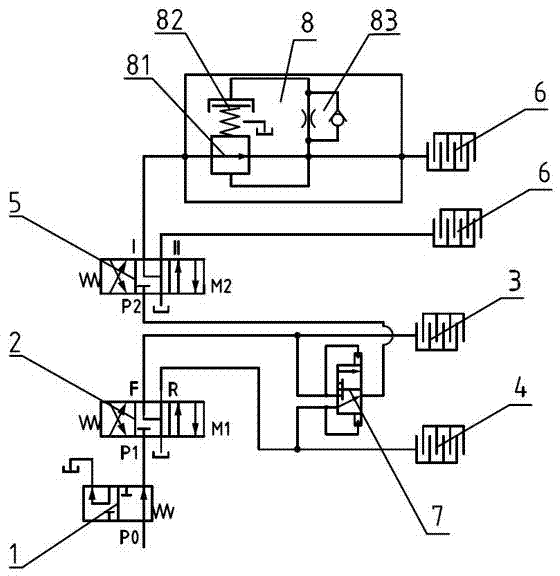
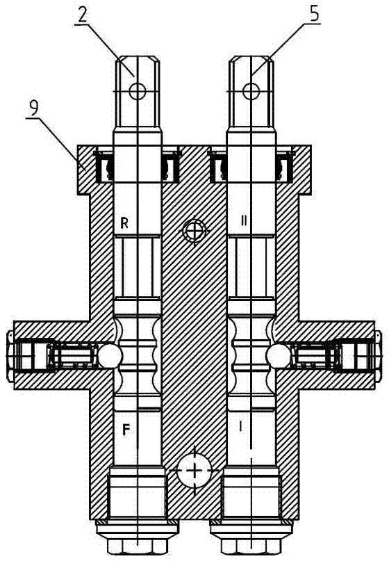
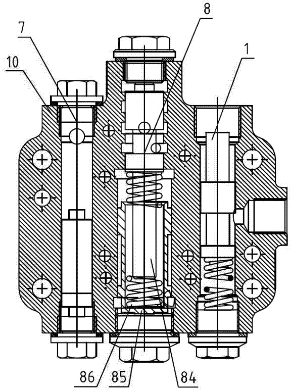
[0014] Such as figure 1 As shown, a power-shift transmission control system includes a cut-off valve 1, a reversing control valve 2, a forward gear clutch 3, a reverse gear clutch 4, a transmission control valve 5, and a transmission clutch 6. The reversing control valve 2 and A shuttle valve 7 is arranged between the shift control valve 5, and a buffer valve 8 is arranged between the shift control valve 5 and the shift clutch 6; the oil flows through the cut-off valve 1 and the reversing control valve 2 to the forward gear clutch 3 or the reverse gear sequentially. Gear clutch 4, two oil outlets of reversing control valve 2 are connected with two oil inlets of shuttle valve 7 respectively, and the oil outlet of shuttle valve 7 is connected with the oil inlet of variable speed control valve 5.

[0015] The oil enters the reversing control valve 2 through the cut-off va...


PUM


Abstract

A power gear-shifting speed-change control system comprises a stop valve, a reversing operating valve, a forward gear clutch, a backward gear clutch, a speed-change operating valve and a speed-change clutch. A shuttle valve is arranged between the reversing operating valve and the speed-change operating valve, a cushion valve is arranged between the speed-change operating valve and the speed-change clutch, oil sequentially passes through the stop valve and the reversing operating valve to flow to the forward gear clutch or the backward gear clutch, two oil outlets of the reversing operating valve are connected with two oil inlets of the shuttle valve respectively, and an oil outlet of the shuttle valve is connected with an oil inlet of the speed-change operating valve. The power gear-shifting speed-change control system has the advantages that whether buffering is performed is determined according to the pressure building characteristics of every clutch, different pressure building characteristics can be obtained according to every speed gear and different requirements of different machine types, and accordingly gear pressure control systems do not influence each other.

Description

technical field [0001] The invention relates to a shifting control system for power shifting of a walking machine, in particular to a mechanically controlled power shifting shifting control system. Background technique [0002] At present, power shifting is widely used in the transmission system of construction machinery. Basically, the hydraulic slide valve is used to control the oil circuit of the gearbox clutch to realize gear shifting. This kind of on-off control of the oil circuit will bring a large Shifting shock, if the shock is too large, it will affect the operating comfort of shifting and the life of parts. In order to solve the impact phenomenon during the shifting process, it is mainly to install a buffer device in the main oil circuit. Before the hydraulic oil enters the clutch of each gear, the oil pressure is buffered to delay the pressure build-up time. Although this solution has played a role to a certain extent The function of buffering, but because the bu...

Claims


Application Information

Patent Timeline
Patent Type & Authority Applications(China)
IPC IPC(8): F16H61/4008F16H61/46
Inventor 王展罗石忠牛宏杰马志刚张琦
Owner JIANGSU LIUGONG MACHINERY
Why Eureka
Try Eureka