
Ground source and air source coupling heat pump system with heat recovery function

A technology of air source heat pump and ground source heat pump, which is applied in the energy recovery system of ventilation and heating, air conditioning system, ventilation system, etc. Problems such as unbalanced support can be achieved to reduce operational complexity, diversify options, and solve regional overcooling or regional overheating effects

Inactive Publication Date: 2013-07-10
UNIV OF SHANGHAI FOR SCI & TECH
View PDF2 Cites 6 Cited by
  • Summary
  • Abstract
  • Description
  • Claims
  • Application Information

AI Technical Summary

Problems solved by technology

[0008] The invention discloses a ground source and air source coupled heat pump system with heat recovery function, the purpose of which is to overcome the system soil heat (cold) accumulation caused by the existing ground source heat pump system and compound ground source heat pump system , Unbalanced soil income and expenditure, limited operating conditions of air source heat pump, compound ground source heat pump with complex structure, low efficiency, difficult to control and other application defects, changing the disadvantages of auxiliary reheating of traditional air conditioning treatment units

Method used


Image

  • Ground source and air source coupling heat pump system with heat recovery function

Examples


Embodiment Construction

[0021] The present invention will be described in further detail below in conjunction with the accompanying drawings. Take Shanghai as an example to describe (the specific usage mode is selected according to the different regions)

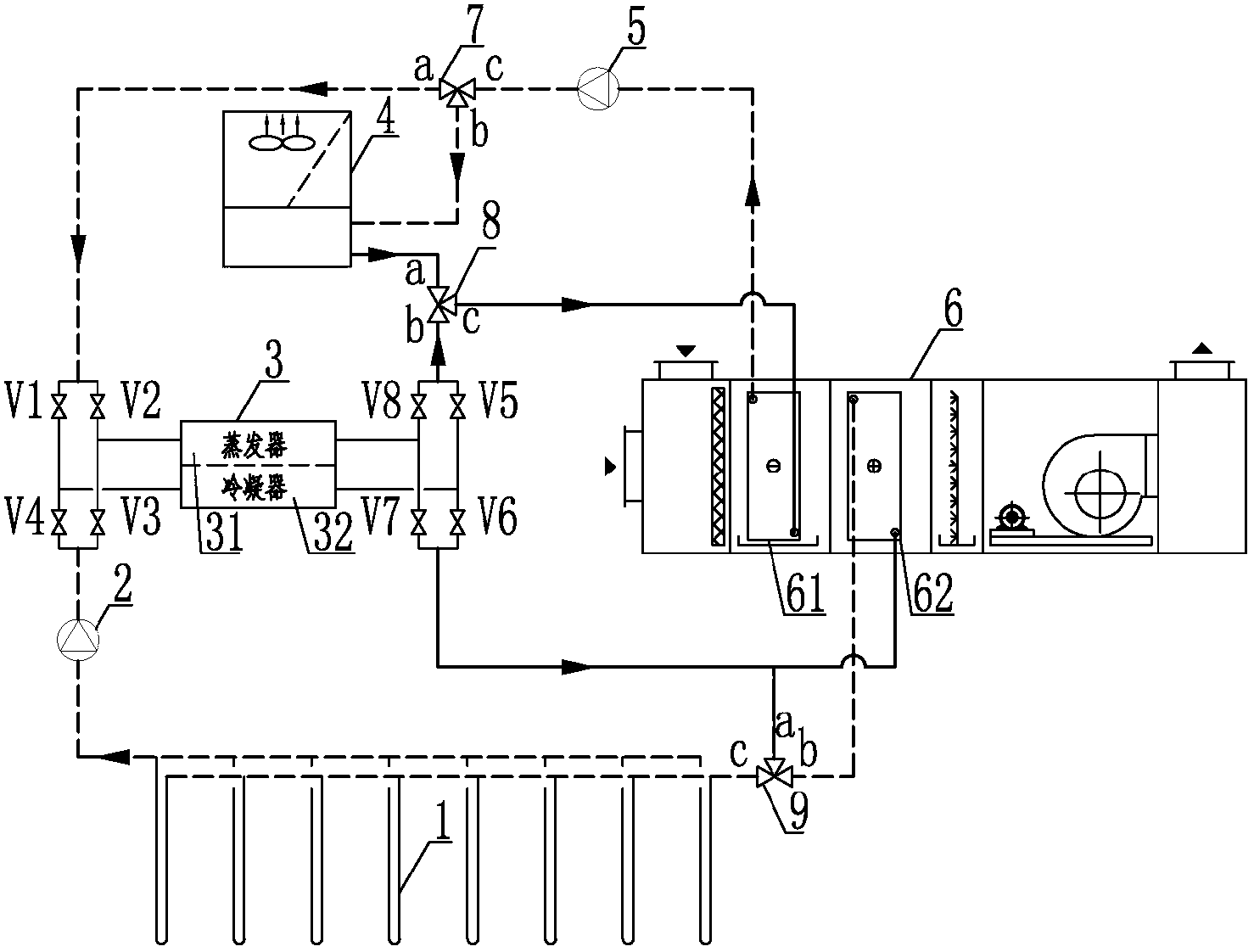
[0022] A ground source and air source coupled heat pump system with heat recovery function, such as figure 1 As shown, it includes ground source heat pump 3, air source heat pump 4, water supply three-way regulating valve 8, return water three-way regulating valve 7, cold and hot water pump 5, cooling water pump 2, air handling unit 6, heat recovery three-way regulating valve 9 , the eight mode switching valves V1-V8 of the ground source heat pump, and the buried pipe 1.

[0023] The ground source heat pump 3 is mainly composed of a compressor, a condenser 32 , an expansion valve, and an evaporator 31 connected in a conventional heat pump system.

[0024] The air source heat pump 4 is mainly composed of a compressor, a condenser, an expansion val...


PUM


Abstract

A ground source and air source coupling heat pump system with a heat recovery function comprises a ground source heat pump, an air source heat pump, an air processing unit and an embedded pipe, wherein at the load side: a surface cooling section water outlet of the air processing unit is connected with a cold-hot water pump and divided into two paths through an end c of a water return three-way adjusting valve, and one path is communicated with an end b of a water supply three-way adjusting valve b through a ground source heat pump evaporator; the other path is led to the end b from the end c of the water return three-way valve c and communicated with an end a of the water supply three-way adjusting valve; the two paths are switched into the surface cooling section after being collected at the end c of the water supply three-way adjusting valve; one a cold-hot source side: a water outlet pipe end of the embedded pipe is connected with a cooling water pump and divided into two paths after passing through a mode conversion valve V6 of a ground source heat pump condenser, one path is directly connected with an end a of a heat recovery three-way adjusting valve, and the other path is communicated with an end b of the heat recovery three-way adjusting valve after entering a reheating section; and the two paths are connected with a water inlet pipe end of the embedded pipe after being collected at an end c of the heat recovery three-way adjusting valve. The ground source and air source coupling heat pump system with the heat recovery function has the advantages that control is flexible, diver in selection, energy conservation in operation and the like.

Description

technical field [0001] The invention relates to a ground source and air source coupled heat pump system with heat recovery function, belonging to the technical field of cold and heat source utilization. Background technique [0002] With the rapid development of my country's economy, building energy consumption will increase day by day with the growth of building area. Among them, reducing the energy consumption of HVAC and domestic hot water systems is of vital significance to alleviate environmental pollution and resource shortage. [0003] Although the ground source heat pump system has a higher energy efficiency ratio compared with conventional air conditioning systems; it is a renewable energy source that can alleviate energy shortages, but in the current utilization of ground source heat pumps, due to the lack of research on the balance of cold and heat in existing projects And the lack of monitoring of the impact on the environment results in the accumulation of grou...

Claims


Application Information

Patent Timeline
IPC IPC(8): F24F5/00F25B29/00F24F12/00
Inventor 陈剑波亢友立姚晶珊聂琳杰王玉戴晶于海照郭利娜
Owner UNIV OF SHANGHAI FOR SCI & TECH
Learn More