Urinary sediment counting chamber

A technology of counting pool and urine sediment, which is applied in the field of counting pool of urine sediment analysis system, can solve the problem of long time consumption and achieve the effect of convenient cleaning

Active Publication Date: 2013-07-10
URIT MEDICAL ELECTRONICS CO LTD
View PDF8 Cites 7 Cited by
  • Summary
  • Abstract
  • Description
  • Claims
  • Application Information

AI Technical Summary

Problems solved by technology

Although a clear image can be obtained by using the above-mentioned structure counting cell for detection and counting, since the cells and other formed components in the sample liquid are naturally settled by gravity, it takes 2 to 5 minutes to make the cells, crystals, tubes and so on in the sample liquid Formed components such as type are completely settled on the base, which takes a long time

Method used


Image

  • Urinary sediment counting chamber
  • Urinary sediment counting chamber
  • Urinary sediment counting chamber

Examples


Embodiment Construction

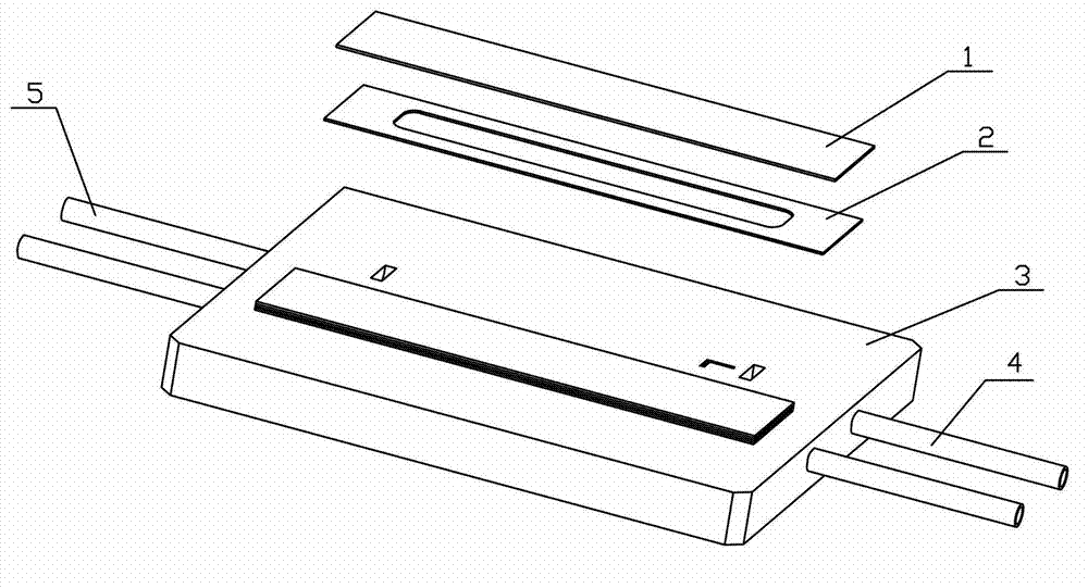
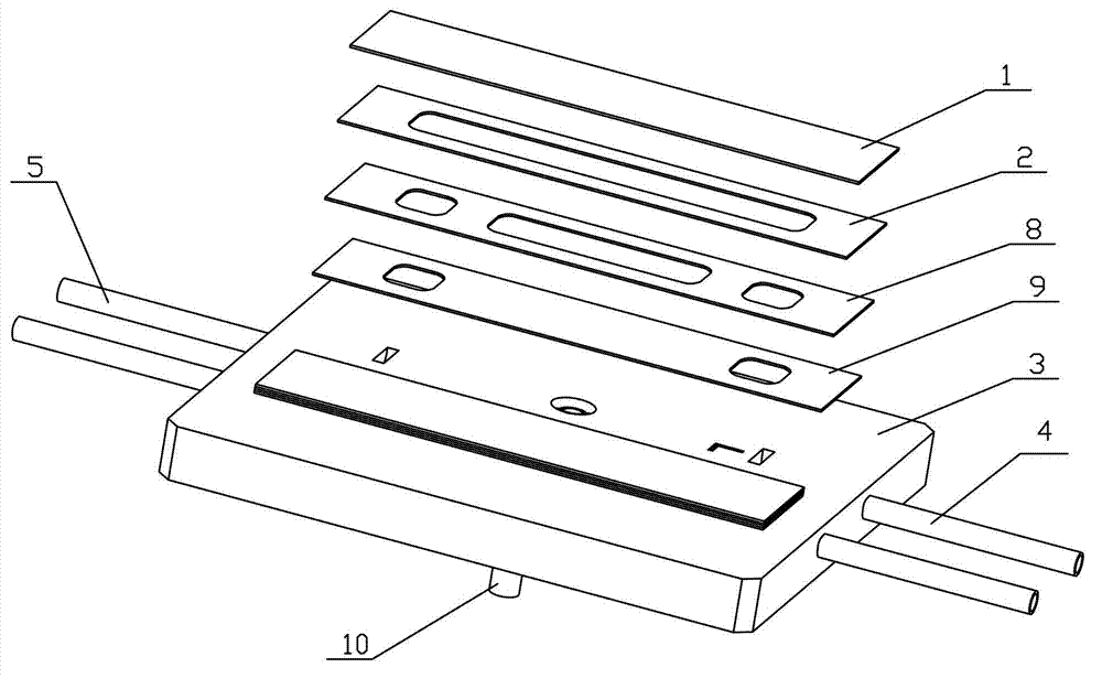
[0029] Figure 3-6 It is a diagram illustrating the first embodiment of the present invention. see Figure 3-6 , the urine sediment counting tank of the present invention includes a base 3, the base 3 is provided with a bottom solid-phase support structure, a partition glass 2 and a fixed slide 1 from the bottom to the top, and the center of the partition glass 2 is provided with an opening ,in:

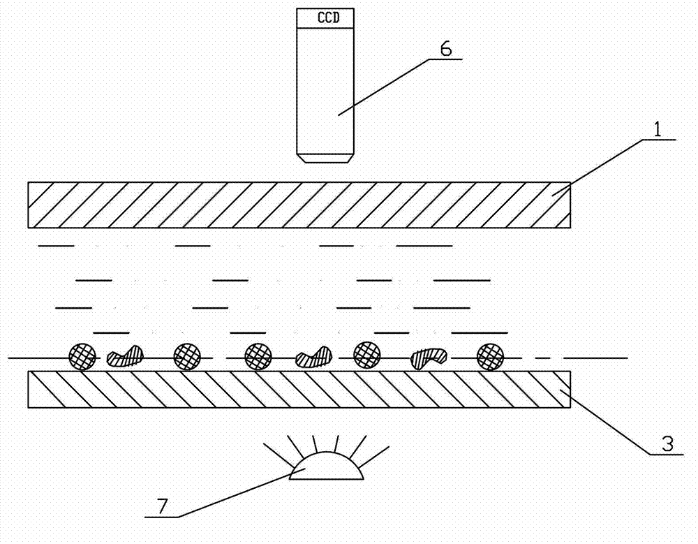
[0030] The bottom solid-phase support structure is made up of a transparent silica gel plate 9 placed on the lower floor, and a silica gel pressing sheet 8 placed on the transparent silica gel sheet 9, and an opening is provided on the silica gel pressing sheet 8 (the opening is located on the spacer glass 2 Within the range of the orthographic projection of the upper opening), a cavity is formed after the base 3, the transparent silica gel plate 9, the silica gel pressing sheet 8, the spacer slide 2 and the fixed slide 1 are bonded together by optical glue , for detecting the inn...


PUM


Abstract

The invention discloses a urinary sediment counting chamber which comprises a base, wherein a bottom solid phase supporting structure, an isolation slide and a fixing slide are arranged on the base from bottom to top; an opening is formed in the isolation slide; the bottom solid phase supporting structure consists of a lower transparent silica gel plate and a silica gel pressing sheet arranged on the lower transparent silica gel plate; an opening is formed in the silica gel pressing sheet; the base, the transparent silica gel plate, the silica gel pressing sheet, the isolation slide and the fixing slide are stuck together to form a cavity serving as a detection inner cavity; channels for enabling sample liquid to be in and out of the detection inner cavity are formed on the transparent silica gel plate and the silica gel pressing sheet; a sample inlet hole and a sample outlet hole which are communicated with the channels are respectively formed in the base and are respectively connected with a sample inlet pipe and a sample outlet pipe; a working channel is arranged on the base; and as force is applied by the working channel, the bottom solid phase supporting structure can do reciprocating motion in the detection inner cavity. The counting chamber can quickly fix visible components such as cells in the sample liquid on a plane, so that a user can observe the visible components with a microscope conveniently.

Description

technical field [0001] The invention relates to the technical field of urine microscope and blood microscope detection, in particular to a counting pool of a urine sediment analysis system. Background technique [0002] In the current urine sediment analysis system using flow microscopy, the structure of the counting pool used is as follows: figure 1 (for the dual-channel counting pool), including a base, a partition glass arranged on the base and an upper slide (i.e. a fixed slide) arranged on the partition slide, wherein the base and the upper slide are fixed There is an opening in the center of the spacer, and a cavity is formed after the base, spacer and upper glass are glued together, which is the detection cavity; there is a cavity on the base that communicates with the detection cavity. These holes are respectively connected with the injection tube and the sample outlet tube. The detection process is as follows: the sample liquid enters the detection cavity through ...

Claims


Application Information

Patent Timeline
Patent Type & Authority Applications(China)
IPC IPC(8): G01N15/10
Inventor 唐雪辉农柳华
Owner URIT MEDICAL ELECTRONICS CO LTD
Why Eureka
Try Eureka