Double thrust electromagnet damping mechanism

A shock-absorbing mechanism and electromagnet technology, applied in the direction of electromagnets and electromagnets with armatures, can solve the problems of limited impact life and other problems, and achieve the effects of improving life expectancy, avoiding excessive impact sound and good buffering effect.

Active Publication Date: 2016-03-30
THYSSENKRUPP ELEVATORS SHANGHAI CO LTD
View PDF9 Cites 0 Cited by
  • Summary
  • Abstract
  • Description
  • Claims
  • Application Information

AI Technical Summary

Problems solved by technology

Although a multi-stage (two-stage) shock-absorbing mechanism is used to prolong the service life of the shock-absorbing pad, the shock-absorbing pad is inside the electromagnet. When replacing, the brake arm and the electromagnet need to be disassembled, and the design is only On the basis of the original shock-absorbing sheet, a columnar shock-absorbing pad of elastic material is added. Although its service life is increased, the original shock-absorbing sheet and the newly added columnar shock-absorbing pad are both elastic materials, and its impact life still limited

Method used


Image

  • Double thrust electromagnet damping mechanism
  • Double thrust electromagnet damping mechanism
  • Double thrust electromagnet damping mechanism

Examples


Embodiment 1

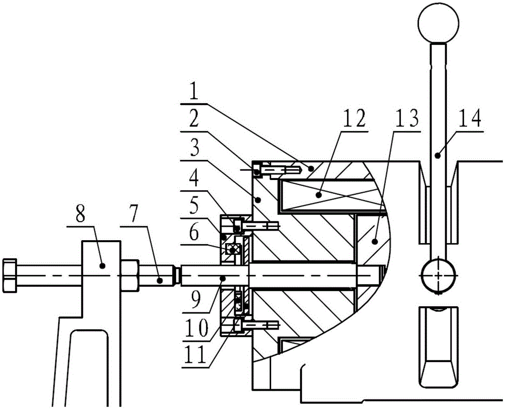
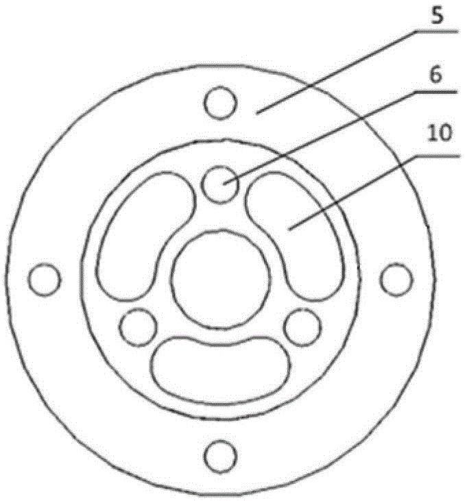
[0029] Such as figure 1 and figure 2 As shown, this embodiment is applied to a conventional electromagnetic braking elevator traction machine. Such as figure 2 As shown, the damping mechanism in this embodiment is symmetrically sleeved on the outside of the push rod 9 and arranged outside the electromagnet core 3. The damping mechanism on each side includes: a cover plate 5 and a bumper that are oppositely arranged and form a cavity. Plate 11, and the shock absorber 10 of the primary shock absorber and the shock absorber 6 of the secondary shock absorber which are arranged in the cavity and are composed of several shock absorbers, wherein: the cover plate 5 is fixedly connected with the iron core 3, The striking plate 11 is movably arranged between the cover plate 5 and the iron core 3, and the shock absorbing block 10 of the primary shock absorbing pad and the shock absorbing block 6 of the secondary shock absorbing pad are arranged centrally symmetrically with the push r...

Embodiment 2

[0039] Such as Figure 7 As shown, the multistage shock absorber of the present embodiment is a three-stage structure, wherein: the shock absorber 10 of the primary shock absorber, the shock absorber 6 of the secondary shock absorber, and the shock absorber 17 of the third stage shock absorber They are evenly distributed in the cover plate 5 in a centrally symmetrical manner, and the hardness of each level of shock absorbing pad and the height extending to between the cover plate 5 and the strike plate 11 are not the same, and the higher the hardness of the shock absorbing pad, it extends to the cover plate The height between the plate 5 and the strike plate 11 becomes smaller.

Embodiment 3

[0041] Such as Figure 8 As shown, the multistage shock absorber in this embodiment adopts any one of the following three implementations:

[0042] a) if Figure 8As shown in (a), the shock absorbing block 10 of the primary shock absorbing pad is inserted or screwed into the cover plate 5 , and the shock absorbing block 6 of the secondary shock absorbing pad is inserted or screwed into the striking plate 11 .

[0043] b) if Figure 8 As shown in (b), the shock absorber 10 of the primary shock absorber is inserted or screwed into the strike plate 11 , and the shock absorber 6 of the secondary shock absorber is inserted or screwed into the cover plate 5 .

[0044] c) if Figure 8 As shown in (c), the two-stage shock absorbing pads 10 and 6 are inserted or screwed into the striking plate 11 .


PUM

PropertyMeasurementUnit
tensile strengthaaaaaaaaaa

Abstract

The invention discloses a dual-thrust electromagnet damping mechanism, and belongs to the technical field of elevator traction machines. The damping mechanism is symmetrically sleeved on the outside of a push rod and arranged on the outside of an electromagnet core. The damping mechanism on each side comprises a cover plate, a striking plate and multiple stages of damping pads, wherein the cover plate and the striking plate are oppositely arranged to form a cavity, and the multiple stages of damping pads are arranged in the cavity; each stage of damping pad in the multi-stage damping pad is composed of a plurality of damping blocks, the damping blocks are centrosymmetrically arranged through taking the push rod as a central shaft, and the two sides of each damping block are respectively in vertical contact with the cover plate and the striking plate; and each stage of damping pad at least contains two independent columnar structures. According to the invention, because mutually-separated multi-body damping pads are adopted, the damping pads can be repaired or replaced without adjusting key components such as braking arms and electromagnets and the like; and due the application of a multi-stage damping principle, the damping pads are effectively protected while low noises are ensured, so that a situation that the damping pads are over-impacted is avoided, thereby greatly prolonging the service life of the damping pads.

Description

technical field [0001] The invention relates to a device in the technical field of elevator traction machines, in particular to a double-thrust electromagnet damping mechanism for the traction machine. Background technique [0002] The safety and reliability of elevator equipment in buildings is extremely important, and the traction machine brake (including electromagnet, brake arm, adjusting bolt and other components) as an elevator safety component is the top priority. At present, the elevator traction machines are shipped after installation and commissioning by the workshop production personnel. In order to ensure the quality of the traction machines, the on-site personnel are required not to disassemble the traction machines at will. However, since the damping pad of the electromagnet of the traction machine is prone to failure, it often needs to be disassembled and replaced on site, and the disassembly and replacement process is often completed by on-site operators, whi...

Claims


Application Information

Patent Timeline
Patent Type & Authority Patents(China)
IPC IPC(8): H01F7/12
Inventor 许林安周国卫
Owner THYSSENKRUPP ELEVATORS SHANGHAI CO LTD
Why Eureka
Try Eureka