
Linkage composite brake structure of switch, switch and electric tool

A technology of electric tools and switches, applied in the direction of electric switches, circuits, electrical components, etc., can solve the problems of short service life of the brake structure, achieve the effects of prolonging service life, reducing serious wear and tear, and low manufacturing cost

Active Publication Date: 2015-10-28
SHANGHAI BAICHENG ELECTRONICS
View PDF4 Cites 0 Cited by
  • Summary
  • Abstract
  • Description
  • Claims
  • Application Information

AI Technical Summary

Problems solved by technology

[0006] The purpose of the present invention is to provide a linkage composite brake structure of a switch, a switch and an electric tool, so as to solve the problem of short service life of the brake structure caused by single-contact contact brake ignition in the prior art

Method used


Image

  • Linkage composite brake structure of switch, switch and electric tool
  • Linkage composite brake structure of switch, switch and electric tool
  • Linkage composite brake structure of switch, switch and electric tool

Examples


Embodiment Construction

[0026] The embodiments of the present invention will be described in detail below with reference to the accompanying drawings, but the present invention can be implemented in a variety of different ways defined and covered by the claims.

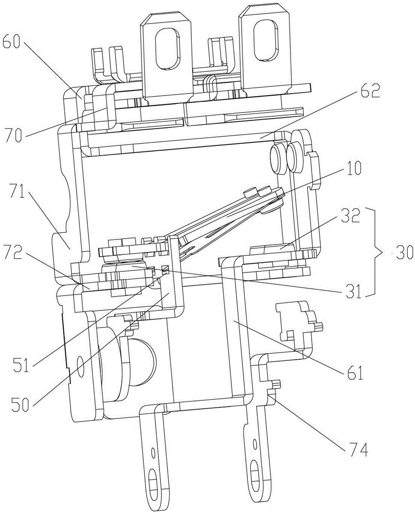
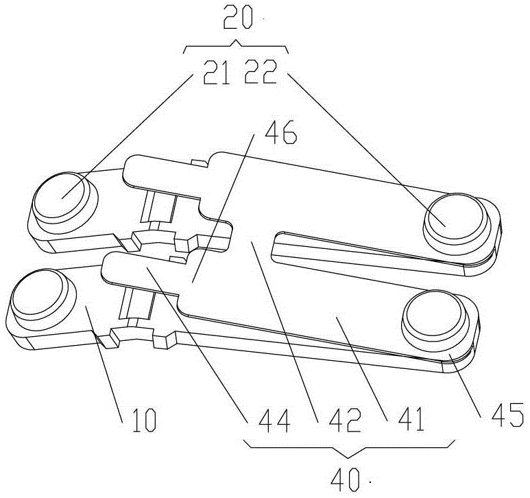
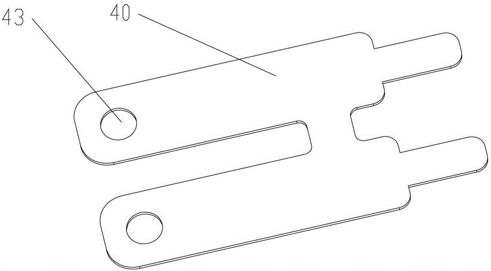
[0027] As the first aspect of the present invention, a switch linkage compound brake structure is provided. Such as Figure 1 to Figure 3 As shown, the linkage composite brake structure includes: a plurality of movable contact bridges 10, which are arranged side by side and spaced in sequence; a flexible metal sheet 40, the plurality of movable contact bridges 10 are connected by the elastic metal sheet 40; The contact 20, the plurality of movable contacts 20 includes a plurality of brake movable contacts 21 and a plurality of running movable contacts 22, the first end of each movable contact bridge 10 is provided with a brake movable contact 21, and each movable contact The second end of the bridge 10 is provided with a running movable contact...


PUM


Abstract

A linked composite brake structure for a switch, the switch and an electric tool. The linked composite brake structure comprises: a plurality of moving contact bridges (10), elastic metal sheets (40), a plurality of moving contact heads (20) and a plurality of static contact heads (30), wherein the plurality of moving contact bridges are sequentially arranged in parallel and at intervals; the plurality of moving contact bridges are connected by virtue of the elastic metal sheets; the plurality of moving contact heads comprise a plurality of brake moving contact heads (21) and a plurality of running moving contact heads (22), a brake moving contact head is arranged at the first end of each of the moving contact bridges, and a running moving contact head is arranged at the second end of each of the moving contact bridges; and the plurality of static contact heads comprise a plurality of brake static contact heads (31) arranged by being in one-to-one correspondence with the plurality of brake moving contact heads, and a plurality of running static contact heads (32) arranged by being in one-to-one correspondence with the plurality of running moving contact heads. Because the plurality of moving contact bridges are connected by virtue of the elastic metal sheets, during braking, the plurality of moving contact heads are closed with the plurality of static contact heads, and multi-point ignition is realized, thus reducing the problem of serious wear of the contact heads during single-point contact braking, and then prolonging the service life of the linked composite brake structure.

Description

Technical field [0001] The present invention relates to the field of switch devices, and more specifically, to a linkage compound brake structure of a switch, a switch and an electric tool. Background technique [0002] At present, the brake structure in power tools is mainly divided into two categories: electronic brakes and mechanical brakes. Electronic brakes are rarely used due to their high cost, high requirements on the circuit system, and easy to produce unstable conditions. Traditional mechanical brakes are widely used in switches. [0003] The mechanical brakes in the prior art are divided into the following structures: push contact type, side contact type, and rocker contact type. [0004] The brake structures in the prior art are all single-contact brakes, that is, during the braking process, a brake moving contact is in contact with a brake static contact, so that the two input ends of the motor are short-circuited to realize braking. . With the continuous improvement ...

Claims


Application Information

Patent Timeline
Patent Type & Authority Patents(China)
IPC IPC(8): H01H1/20
CPCH01H1/2025H01H1/26H01H9/40
Inventor 蔡颖杰
Owner SHANGHAI BAICHENG ELECTRONICS
Learn More