Hydraulic axis

A hydraulic shaft, hydraulic technology, applied in the direction of presses, fluid pressure actuation devices, servo motors, etc., can solve problems such as large prestressing equipment costs and so on

Active Publication Date: 2013-07-10
ROBERT BOSCH GMBH
View PDF8 Cites 11 Cited by
  • Summary
  • Abstract
  • Description
  • Claims
  • Application Information

AI Technical Summary

Problems solved by technology

The disadvantage is that at least two valves must be effectively connected in this hydraulic axis based on the respective duty cycle segment
In addition, the necessary prestressing requires a large equipment outlay

Method used


Image

  • Hydraulic axis
  • Hydraulic axis
  • Hydraulic axis

Examples


Embodiment Construction

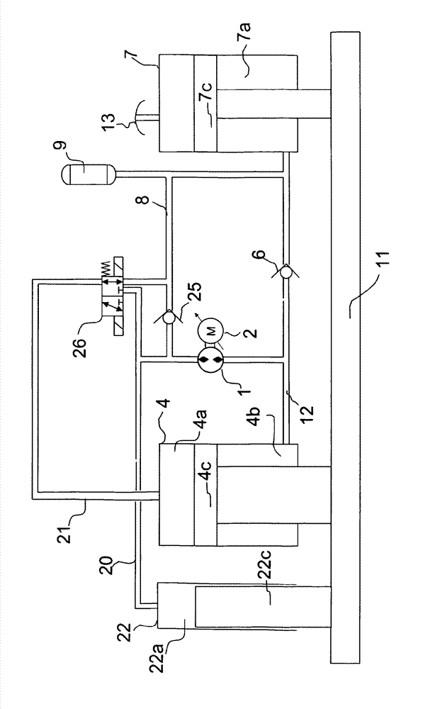
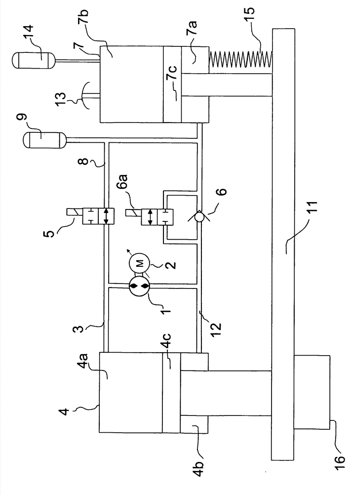
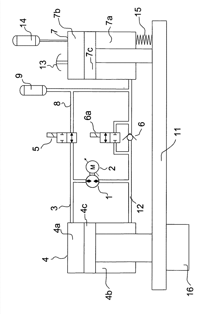
[0066] FIG. 1 shows a schematic circuit diagram of a hydraulic drive device in a static state according to a preferred first embodiment of the present invention.

[0067] As can be seen from all the figures, the hydraulic drive according to the invention has a pump in the form of a variably driven hydraulic machine 1 which is here mechanically connected to an electric motor 2 . The hydraulic machine 1 is connected at its two pressure connections to a hydraulic pressure line system which forms a closed hydraulic circuit.

[0068] In particular, a connecting line 3 is connected to the first pressure connection of the hydraulic machine 1 , which leads directly to the piston-side pressure chamber 4 a of the master cylinder 4 . Connected to the second pressure connection of the hydraulic machine 1 is a second line 12 , which is connected to a pressure chamber 4 b on the piston rod side of the master cylinder 4 (hereinafter referred to as annular chamber 4 b ). Furthermore, line 12...


PUM


Abstract

The invention relates to a hydraulic axle comprising a hydraulic cylinder having a cylinder chamber and having a ring chamber, which are delimited from each other by a cylinder piston. Said hydraulic axle further comprises a hydraulic control assembly via which the hydraulic cylinder can be actuated in a rapid stroke movement and in a power stroke movement. The control assembly comprises a hydro machine, the conveyance direction of which is reversible and which is fluidically connected to the ring chamber, a fluid container, a locking valve via which a connection between the fluid container and the cylinder chamber can be blocked and enabled and a feeder valve which, due to the arrangement thereof, allows for a suctioning of fluid out of the fluid container on the connection of the hydro machine connected to the ring chamber. The fluid container has a chamber having an adjustable volume, designed so that a reduction of said volume causes a displacement of fluid out of the fluid container, and a volume adjustment element of the fluid container is mechanically coupled to the cylinder piston.

Description

technical field [0001] The invention relates to a hydraulic shaft. Within the framework of the present application, a hydraulic axis is to be understood as meaning a hydraulic actuator, for example a hydraulic cylinder, and a hydraulic or electrohydraulic control device which actuates the actuator with a fluid. Such hydraulic axes are compact, robust and powerful drives. This hydraulic axis can be used in various industrial automation applications, such as presses, plastic machines, edge benders, etc. Background technique [0002] Such a drive is designed in particular to realize at least two motion sequences, namely a rapid switching motion, referred to below as rapid motion or rapid travel, and a force-applying working motion, referred to below as working travel or as a pressing operation. [0003] The applicant's application DE 10 2009 043 034 describes a known hydraulic shaft. In a prestressed hydraulic system, the master cylinder, the quick-shift cylinder and the rev...

Claims


Application Information

Patent Timeline
Patent Type & Authority Applications(China)
IPC IPC(8): B30B15/16F15B11/024
CPCB30B15/161F15B7/006F15B11/022F15B2211/20515F15B2211/20561F15B2211/27F15B2211/625F15B2211/7107F15B11/024Y02P80/10
Inventor H.戈特弗里德
Owner ROBERT BOSCH GMBH
Why Eureka
Try Eureka