AI technical title is built by Patsnap AI team. It summarizes the technical point description of the patent document.
A rack and frame technology, applied in the substation/switchgear frame, electrical components, substation/switch layout details, etc., can solve the problem of insufficient hardness of the switchgear, reducing the conductivity of the frame parts, corrosion resistance, expensive work protection measures, etc. question
Inactive Publication Date: 2013-07-10
C E S CONTROL ENCLOSURE SYST
View PDF9 Cites 7 Cited by
Summary
Abstract
Description
Claims
Application Information
AI Technical Summary
This helps you quickly interpret patents by identifying the three key elements:
Problems solved by technology
Method used
Benefits of technology
Problems solved by technology
[0011] The welding process used to join the frame parts produces corrosion by burning in the region of the weld seam, which locally destroys the coating of the frame parts and may thus reduce the desired electrical conductivity and / or corrosion resistance of the frame parts sex
In addition, some coatings may adversely affect the welding process, making it necessary to free the structural components to be joined from coatings prior to the welding process.
[0012] For the purpose of avoiding corrosion or ensuring improved electrical conductivity of the frame parts, the only remaining possibility is to apply or repair a suitable coating after the welding process, which involves additional costs and increased time during the manufacturing and assembly process expenditure
[0013] Last (but not least) it should be mentioned that the disadvantages of welding are: not only high energy requirements but also expensive work protection measures for welding personnel
[0016] However, even in this embodiment, if the switchgear is moved by a crane, the problem arises of insufficient rigidity of the switchgear against deformation, so that it may be necessary to provide additional elements in order to ensure sufficient stability of the frame
Method used
Image
Click on the blue label to locate the original text in one second.
Reading with bidirectional positioning of images and text.
Examples
Embodiment Construction
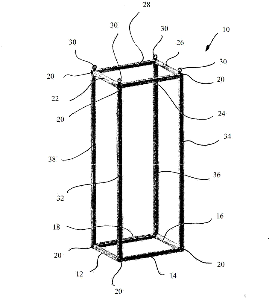
[0064] figure 1 A switchgear cabinet frame according to the invention, generally designated with the reference numeral 10 , is shown schematically. In the embodiment shown, the switchgear frame rack 10 comprises four downstream horizontal frame elements 12, 14, 16 and 18 forming a rectangle, and four upstream horizontal frame elements 22, 24, 26 and 28 also forming a rectangle. and four vertical frame members 32, 34, 36 and 38 connecting the two rectangles. The frame pieces are interconnected in the corner regions of the switch cabinet frame rack by so-called “corner connectors” 20 , in the illustrated embodiment forming a right angle between each pair of interconnected frame pieces. All frame members without exception are formed along the longitudinal axis L (eg figure 2 and image 3 Shown) an extended cylindrical hollow profile 42 is formed, and the cylindrical hollow profile 42 will be described in detail below.
[0065] In addition, if Figure 5 As shown, the upper c...
PUM
Abstract
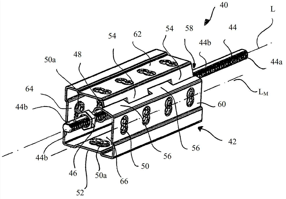
The invention relates to a rack (10) comprising a plurality of frame pieces (12, 14, 16, 18, 22, 24, 26, 28, 32, 34, 36, 36) that can be interconnected, every frame piece being a cylindrical hollow profile (42; 142) which extends along its longitudinal axis (L) and the lateral axes (L) of two interconnected frame pieces being positioned at a right angle relative to each other. The rack (10) further comprises, for the purpose of interconnecting several frame pieces (22, 24, 32), at least one bracing unit (40) that is capable of bracing a first frame piece (22, 24, 32) against at least one second frame piece or against at least one corner connector (20) interposed between the frame pieces (22, 24, 32) to be interconnected. The bracing unit (40) comprises at least one separately configured bracing element (44) which extends substantially across the entire length of the first frame piece (22, 24, 32), and two force transmission elements (46) associated with the bracing element (44), said force transmission elements transmitting a bracing force of the bracing element (44) onto the components of the rack (10) to be braced against each other, the bracing force being effective in the direction of the longitudinal axis (L) of the first frame piece (22, 24, 32) to be braced, and the bracing force bracing the first frame piece (22, 24, 32) against the at least one second frame piece and / or against the at least one corner connector (20).
Description
technical field [0001] The invention relates to a frame, in particular to a frame constituting a frame for a switch cabinet, which frame comprises a plurality of frame elements which can be interconnected, wherein each frame element is configured as a cylindrical hollow profile (profile) and extend along the longitudinal axis, and wherein the longitudinal axes of the two interconnected frame members are arranged obliquely towards each other. Here, the term "frame" is used to denote support structures, for example for furniture construction and especially for shelving construction, but also other support structures (e.g. bottom frames for machines, support frames for boxes, etc.) . Background technique [0002] The already mentioned switch cabinets are generally used to accommodate electrical and electronic components (eg sensors) of processing plants, machine tools or production plants etc. which are not located directly in or on the machine. Depending on the nature of the...
Claims
Application Information
Patent Timeline
Application Date:The date an application was filed.
Publication Date:The date a patent or application was officially published.
First Publication Date:The earliest publication date of a patent with the same application number.
Issue Date:Publication date of the patent grant document.
PCT Entry Date:The Entry date of PCT National Phase.
Estimated Expiry Date:The statutory expiry date of a patent right according to the Patent Law, and it is the longest term of protection that the patent right can achieve without the termination of the patent right due to other reasons(Term extension factor has been taken into account ).
Invalid Date:Actual expiry date is based on effective date or publication date of legal transaction data of invalid patent.

