Non-power slide recreation facility

A technology of amusement facilities and slideways, which is applied in the field of amusement facilities and non-powered slideway amusement facilities, can solve the problems of increasing operating costs, shortening service life, reducing reliability, etc., and achieves good effects of absorbing impact energy, improving work efficiency, Effect of reducing installation cost

Inactive Publication Date: 2014-07-23
诸暨市新飞娱乐设备制造厂
View PDF4 Cites 0 Cited by
  • Summary
  • Abstract
  • Description
  • Claims
  • Application Information

AI Technical Summary

Problems solved by technology

[0002] The slide in the prior art goes up from the ladder and then slides down from the slanting board. The sliding process is short and not very interesting. Although there are some slide-type entertainment items in some large playgrounds, most of them are It is powered, which increases the operating cost of the amusement facilities, and cannot operate in case of power failure
Since amusement facilities are generally suitable for installation in playgrounds, tourists cannot enjoy the natural scenery of the mountains and fields during their play, and the sliding distance is also limited, so that tourists lack a sense of participation. In order to solve the above problems, some It is suitable for trough slides and pipe rail slides in tourist areas. Compared with trough slides, pipe rail slides are safer
[0003] The tube-rail slideway is a facility erected on the ground with a certain slope for passengers to slide up and down on the slide, including ordinary down slides and jumping down slides. The multiple pipe rails need to be installed at different positions and heights. In the prior art, support columns with different lengths need to be cut and connected to the beams for pipe rail support by welding, so that there are too many welds, which reduces the reliability. Low efficiency, increase installation cost
[0004] Since the height of the support frame of the pipe rail slideway is not adjustable, especially when installing the jumping down slideway, the support frame of the pipe rail needs to be of different heights, and the installer needs to bring tools and materials for on-site assembly, so the installation efficiency is low. Inconvenient to operate
[0005] In the prior art, most of the brake devices of the pipe-rail type slide car are equipped with a brake wheel on the wheel shaft of the tackle, and a brake pad is provided on the outer ring of the brake wheel. The lever is connected, and the force of the brake lever is pulled by the wire to pull the brake pad to rub against the brake wheel to complete the brake. However, during the braking process, the brake pad is easy to lock the brake wheel, so that the pulley stops rolling, and the pulley and the pipe rail slide friction , resulting in wear and tear of the pulley, shortening the service life, and because the contact surface between the pulley and the pipe rail is small, the braking effect is not good
[0006] The trolley used for the tube-rail slideway, the tourists sit directly on the trolley, there is no support plate on the back, and the tourists do not rely on the back, so that the tourists can maintain a posture and cannot relax, which makes the tourists feel uncomfortable. Due to the fast sliding speed of the trolley , especially when there is a curve, the body swings under the action of inertia, and there are no supports on both sides of the body, which is likely to cause safety hazards, and in serious cases, tourists may fall out of the tackle. At the same time, the tackle does not have the function of windshield and sunshade
[0007] The pulley used for the pipe-rail slideway is equipped with a bumper at the front and rear of the pulley. The principle is to use the rubber fixed on the bumper to complete the process of absorbing the impact. The entire contact surface is required to be completely covered by the rubber. The rubber is big enough and strong enough to compress enough to absorb part of the impact energy. This method completely uses rubber to absorb part of the impact energy. The rubber is easily damaged and has a short service life, which increases operating costs and has poor impact energy absorption.

Method used


Image

  • Non-power slide recreation facility
  • Non-power slide recreation facility
  • Non-power slide recreation facility

Examples


Embodiment Construction

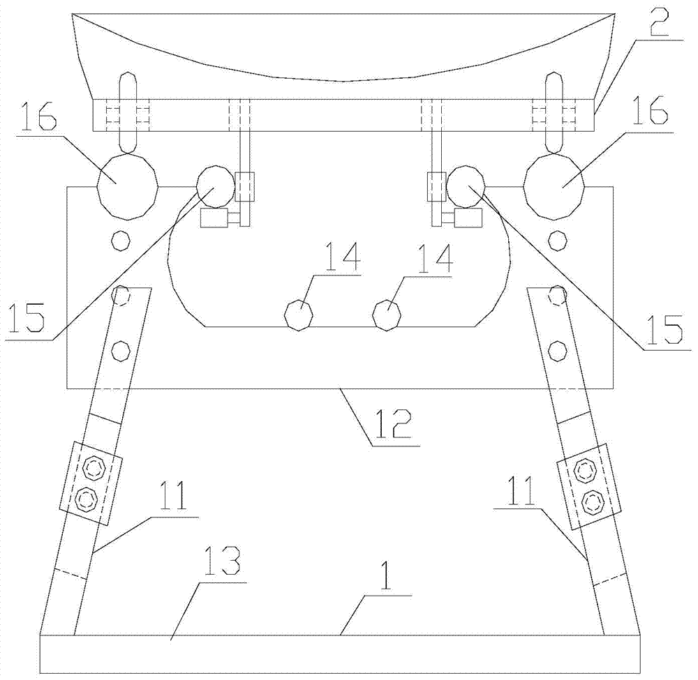
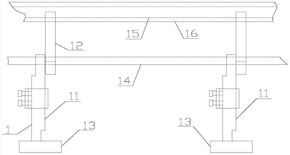
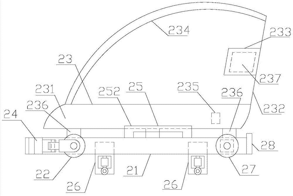
[0028] refer to figure 1 , figure 2 , image 3 , Figure 4 , Figure 5 and Figure 6, a non-powered slideway amusement facility of the present invention, comprising a descending slideway 1 and a trolley 2 matched with the descending slideway 1, the said descending slideway 1 includes several supporting columns 11, several mounting beams 12, several bases 13, a A pipe rail 14, a second pipe rail 15 and a third pipe rail 16, the base 13 is provided with a support column 11, the support column 11 is equipped with a mounting beam 12, and the inner bottom surface of the mounting beam 12 is provided with The first pipe rail 14, the inner side of the installation beam 12 is provided with the second pipe rail 15, and the top of the installation beam 12 is provided with the third pipe rail 16, and the center point of the third pipe rail 16 is connected with the second pipe rail. The center point of the pipe rail 15 is on the same horizontal straight line. The support column 11 in...


PUM


Abstract

The invention discloses a non-power slide recreation facility which comprises a downward slide and a sliding vehicle matched with the downward slide. Compared with the prior art, in the installation process of the slide, height adjustment can be achieved, the working efficiency can be increased, welding connection can be reduced, reliability can be improved, and the installation cost can be lowered; the matched sliding vehicle can prevent sliding vehicle wheels from being abraded, the braking effect is good, the comfort degree can be improved, potential safety hazards can be avoided, and the wind blocking and sun-shading functions can be achieved, the defect that rubber is used independently for impact energy absorption can be avoided, the operating cost is lowered, and the impact energy absorption effect is good.

Description

【Technical field】 [0001] The invention relates to the technical field of amusement facilities, in particular to the technical field of non-powered slideway amusement facilities. 【Background technique】 [0002] The slide in the prior art goes up from the ladder and then slides down from the slanting board. The sliding process is short and not very interesting. Although there are some slide-type entertainment items in some large playgrounds, most of them are It is powered, which increases the operating cost of the amusement facility, and it cannot run in case of a power outage. Since amusement facilities are generally suitable for installation in playgrounds, tourists cannot enjoy the natural scenery of the mountains and fields during their play, and the sliding distance is also limited, so that tourists lack a sense of participation. In order to solve the above problems, some It is suitable for trough slides and pipe-rail slides in tourist areas. Compared with trough slides,...

Claims


Application Information

Patent Timeline
IPC IPC(8): A63G21/04
Inventor 赵海潮
Owner 诸暨市新飞娱乐设备制造厂
Why Eureka
Try Eureka