Multi-force-field dry magnetic separator

A magnetic separator, dry technology, applied in the direction of magnetic separation, solid separation, chemical instruments and methods, etc., can solve the problems of non-magnetic inclusions, unsatisfactory mineral grades, etc., and achieve the effect of avoiding environmental pollution

Active Publication Date: 2013-07-17
CHENGDU LEEJUN IND
View PDF7 Cites 7 Cited by
  • Summary
  • Abstract
  • Description
  • Claims
  • Application Information

AI Technical Summary

Problems solved by technology

[0006] Such solutions have improved the sorting accuracy of minerals to a certain extent, but they have not yet got rid of the solution idea of ​​emphasizing the high strength a

Method used


Image

  • Multi-force-field dry magnetic separator
  • Multi-force-field dry magnetic separator
  • Multi-force-field dry magnetic separator

Examples


Embodiment 1

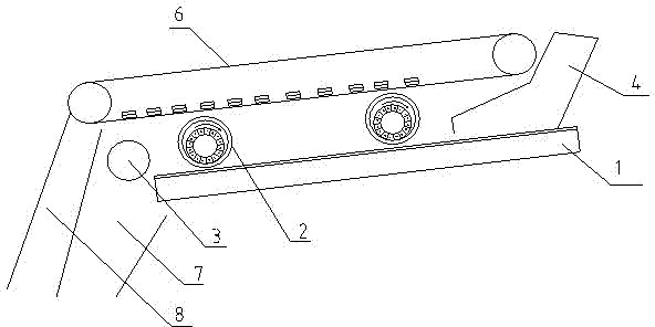
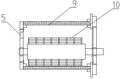
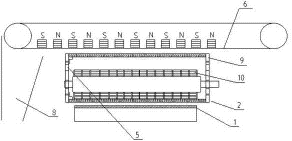
[0033] like figure 1 and figure 2 As shown, a multi-force field dry magnetic separator includes a feeding device 1 and a discharge belt 6 placed above the working surface of the feeding device 1. A magnetic system is installed on the inside of the discharge belt 6. The feeding end of the feeding device 1 The feed port 4 is set, the tailing port 7 is set at the discharge end, the concentrate port 8 is set at the discharge end of the discharge belt 6, and a rotating air-permeable magnetic roller is set between the working surface of the feeding device 1 and the working surface of the discharge belt 6 Cylinder 2, the air-permeable magnetic roller 2 includes a cylinder body 9 and a magnetic system 10 eccentrically arranged in the cylinder body 9, the wrap angle of the magnetic system 10 is 360°, the cylinder body 9 is made of a non-magnetic permeable plate, and The end surface of the cylinder body 9 is provided with an air inlet 5 and connected to the pressure gas. The discharge...

Embodiment 2

[0039] like Figure 4 As shown, this embodiment increases the number of air-permeable magnetic rollers 2 connected in series in the vertical direction on the basis of the first embodiment, that is, the air-permeable magnetic rollers 2a2 are connected in series in the vertical direction of the two air-permeable magnetic rollers 2a1 and 2b1 , 2b2. The sorting process of the materials in this embodiment is similar to that in Embodiment 1, that is, when the materials pass through the air-permeable magnetic rollers 2a1, 2b1, they are adsorbed to the surface of the air-permeable magnetic rollers 2a1, 2b1 and move upwards with them. When the air-permeable magnetic rollers 2a2 and 2b2 are in the magnetic force area, the magnetic material is turned over and adsorbed to its surface, and the non-magnetic material falls on the surface of the feeding device 1 under the action of gravity and wind force and finally falls into the tailings mouth 7, and the magnetic material is connected in se...


PUM

PropertyMeasurementUnit
Wrap angleaaaaaaaaaa

Abstract

The invention discloses a multi-force-field dry magnetic separator. The multi-force-field dry magnetic separator comprises a feeding device, and a discharging belt which is arranged above a working surface of the feeding device, wherein a magnetic system is arranged inside the discharging belt; a charging hole is formed in the charging end of the feeding device; a tailings hole is formed in the discharging end of the feeding device; a concentrate hole is formed in the discharging end of the discharging belt; a rotary breathable magnetic roller cylinder is arranged between the working surface of the feeding device and the discharging belt, and comprises a cylinder body and the magnetic system which is eccentrically arranged in the cylinder body; breathing holes are uniformly formed in the surface of the cylinder body; an air inlet is formed in the cylinder body, and pressure gas is filled into the air inlet; the discharging belt is positioned above a weak magnetic region of the breathable magnetic roller cylinder; and the magnetic field intensity of the magnetic system on the discharging belt is greater than that of the weak magnetic region of the breathable magnetic roller cylinder. According to the multi-force-field dry magnetic separator, wind power is introduced into a material sorting process, so that the magnetic-field-dominant multi-force-field separation is realized, requirements of equipment upsizing are met, and the sorting accuracy of a magnetic material is greatly improved.

Description

technical field [0001] The invention belongs to the technical field of sorting magnetic materials after being ground by grinding equipment in metallurgy, mining, chemical industry and other industries, and in particular relates to a multi-force field dry magnetic separator, especially suitable for materials with a diameter of less than 1mm. Sorting of dry mineral powder. Background technique [0002] Magnetic separation is a treatment method that uses the magnetic difference of the materials to be separated to separate minerals in a magnetic field. Compared with the complicated process and application limitations of wet magnetic separation, dry magnetic separation equipment has the advantages of simple structure, less investment, low operating cost, energy saving and environmental protection, which makes dry magnetic separation equipment develop rapidly in recent years. [0003] With the wide application of high-pressure roller mills in the grinding field, traditional dry m...

Claims


Application Information

Patent Timeline
IPC IPC(8): B03C1/18
Inventor 何亚民魏勇徐智平
Owner CHENGDU LEEJUN IND
Why Eureka
Try Eureka