
Safety device of punch

A technology of safety devices and punching machines, which is applied in safety equipment, metal processing equipment, manufacturing tools, etc., can solve problems such as high risk, inability to use mechanical punching machines, and inability to speed up operation, so as to achieve the effect of increasing production speed

Inactive Publication Date: 2013-07-17
KUNSHAN ANIL PRECISE METAL
View PDF6 Cites 3 Cited by
  • Summary
  • Abstract
  • Description
  • Claims
  • Application Information

AI Technical Summary

Problems solved by technology

[0002] With the rapid development of my country's industry, the use of punching machines is becoming more and more common. Due to the fact that in the processing process, especially the processing of multiple varieties and small batches, most of them are manually operated. During the use of punching machines, various work injuries are often caused by improper safety devices. Accidents, at present, most punching machines use photoelectric sensor switches as safety devices. This device can only be used on electrical control punching machines, and cannot be used on mechanical punching machines. It is extremely dangerous for workers operating on small mechanical punching machines. , workers need to be vigilant all the time during operation, which brings a great mental burden to the operators, and it is impossible to speed up the operation

Method used


Image

  • Safety device of punch
  • Safety device of punch

Examples


Embodiment

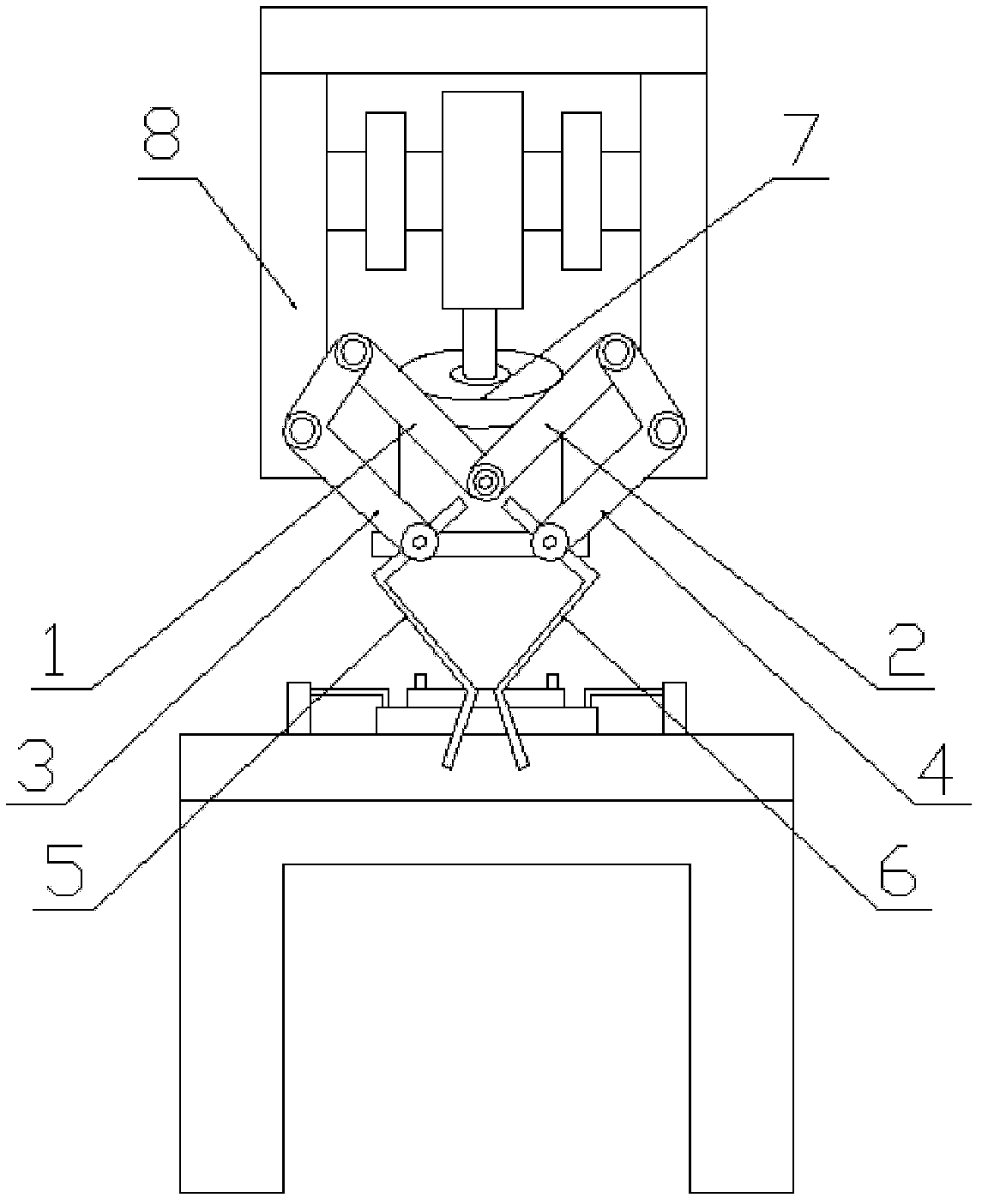
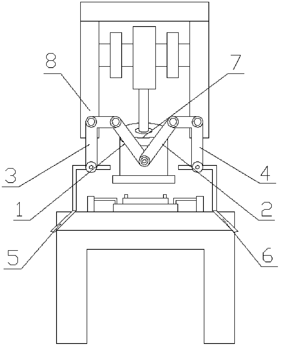
[0013] Embodiment: a safety device for a punching machine, comprising the first, second, third, and fourth connecting rods 1, 2, 3, 4 and the first and second driving rods 5, 6, one end of the first and second connecting rods 1, 2 is respectively connected to The hammer 7 of the punch press is pivotally connected, and the corners of the third and fourth connecting rods 3 and 4 of the L-shape are pivotally connected with the bed 8 of the punch press, and the other ends of the first and second connecting rods 1 and 2 are connected to the third and fourth connecting rods respectively. One end of the rods 3 and 4 is movable and hinged, and the other ends of the third and fourth connecting rods 3 and 4 are fixedly connected with one end of the first and second driving rods 5 and 6 respectively, and the other ends of the first and second driving rods 5 and 6 are located near the press console On the operator's side, the worker's operating arm just stops at the opposite ends of the fi...


PUM


Abstract

The invention discloses a safety device of a punch. The safety device of the punch comprises a first connecting rod, a second connecting rod, a third connecting rod, a fourth connecting rod, a first deflector rod and a second deflector rod, wherein one ends of the first connecting rod and the second connecting rod are respectively hinged with a punch hammer of the punch; turnings of the L-shaped third connecting rod and the L-shaped fourth connecting rod are hinged with the body of the punch; the other ends of the first connecting rod and the second connecting rod are respectively and movably hinged with one ends of the third connecting rod and the fourth connecting rod; the other ends of the third connecting rod and the fourth connecting rod are respectively and fixedly connected with one ends of the first deflector rod and the second deflector rod; the other ends of the first deflector rod and the second deflector rod are located at one side of an operating floor of the punch, which is near an operator; and arms of the operator stop at both mutually deviating sides of the other ends of the first deflector rod and the second deflector rod. According to the safety device of the punch disclosed by the invention, through arranging a connecting rod mechanism driven by the punch hammer on the punch, when the punch hammer falls, the first deflector rod and the second deflector rod of the connecting rod mechanism automatically push aside the arms of the operator to enable the arms of the operator to automatically be away from the lower side of the punch hammer, and thus, even if the operator forgets to leave the arms from the lower side of the punch hammer by misoperation, the first deflector rod and the second deflector rod can automatically push aside the arms of the operator so as to avoid work injury occurring, and therefore, the increase of the production rate is facilitated.

Description

technical field [0001] The invention relates to a safety device, in particular to a punching machine safety device. Background technique [0002] With the rapid development of my country's industry, the use of punching machines is becoming more and more common. Due to the fact that in the process of processing, especially the processing of multiple varieties and small batches, most of them are manually operated. During the use of punching machines, various work-related injuries are often caused by improper safety devices. Accidents, most of the punch presses currently use photoelectric sensor switches as safety devices. This device can only be used on punch presses controlled by electrical appliances, and cannot be used on mechanical punch presses. It is extremely dangerous for workers operating on small mechanical punch presses. , Workers need to be vigilant all the time during operation, which brings a great mental burden to the operators, and it is impossible to speed up th...

Claims


Application Information

Patent Timeline
IPC IPC(8): B21D55/00
Inventor 林志昆
Owner KUNSHAN ANIL PRECISE METAL
Learn More