Method for processing external spiral slot with large screw pitch by numerically controlled lathe and process device

A CNC lathe and helical groove technology, which is applied to milling devices, metal processing equipment, and milling machine equipment that can be installed on machine tools, can solve the problems of large turning tool wear, low yield rate, low efficiency, etc., and reduce the number of tools. Wear, improve yield, high efficiency

Inactive Publication Date: 2013-07-17
王立波
View PDF6 Cites 9 Cited by
  • Summary
  • Abstract
  • Description
  • Claims
  • Application Information

AI Technical Summary

Problems solved by technology

[0002] The processing of the existing external spiral grooves is usually carried out on broaching machines, milling machines or CNC lathes, and the large-pitch external spiral grooves are mostly processed on broaching machines or milling machines. Therefore, the tool wears a lot, the efficiency is low, the yield rate is low, and the cost is high; when the CNC lathe is working, the parts are under power rotation, and the turning tool is a single tool without power drive, and can only move in a straight line with the tool holder. When working, the turning tool is always in cutting state, especially when CNC lathes process external spiral grooves, due to the particularity of spiral groove processing, the wear of the turning tool is greater, and there are problems of low efficiency, low yield, and high cost, and the general transmission ratio of CNC lathes makes The main shaft rotates at a high speed, and it is impossible to process an outer helical groove with a large pitch greater than the matching value of the minimum speed of the main shaft and the maximum moving speed of the tool post.

Method used


Image

  • Method for processing external spiral slot with large screw pitch by numerically controlled lathe and process device
  • Method for processing external spiral slot with large screw pitch by numerically controlled lathe and process device
  • Method for processing external spiral slot with large screw pitch by numerically controlled lathe and process device

Examples


Embodiment Construction

[0040] The present invention will be further described below in conjunction with the accompanying drawings and embodiments.

[0041] refer to figure 1 , the method for CNC lathe processing large-pitch outer spiral groove of the present invention, it comprises the following steps:

[0042] 1) Determine the blank size according to the part drawing;

[0043] 2) According to the part drawing, determine the processing procedure and process size of the part before processing the spiral groove, after processing the spiral groove, and complete the process, and design the process device;

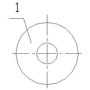
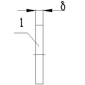
[0044] 3) Calculate the spiral groove lead angle according to the spiral groove size of the part drawing and the process size of the spiral groove, determine the working size of the sheet milling cutter 1 and the transmission ratio of the CNC lathe 14 100~150:1;

[0045] 4) Design the process device including the chip milling cutter 1 and the tool holder 2:

[0046] a) Design the chip milling cu...


PUM


Abstract

The invention relates to a method for processing an external spiral slot with large screw pitch by a numerically controlled lathe and a process device. The method is characterized by comprising the following steps: determining a blank size according to a part drawing; determining process procedures and process dimensions of the blank before spiral slot processing, after spiral slot processing to the end of the process, and designing a process device; calculating a spiral line lift angle theta and process size of the spiral slot, determining working dimensions of a sheet milling cutter and transmission ratio of the numerically controlled lathe; and designing the process device comprising a sheet milling cutter and a knife rest used in the method: providing process parameters required by the method; and programming a control program. For usage, the control program is input to the numerically controlled lathe; the numerically controlled lathe is started, and the spindle and the sheet milling cutter respectively rotate in opposite directions at the same time, and a walking knife rest drives the knife rest and the sheet milling cutter to move forward; and the cutter is retracted after the processing.

Description

technical field [0001] The invention relates to the processing of a helical thread, and relates to a method and a process device for processing a large-pitch outer helical thread groove on a numerically controlled lathe. Background technique [0002] The processing of the existing external spiral grooves is usually carried out on broaching machines, milling machines or CNC lathes, and the large-pitch external spiral grooves are mostly processed on broaching machines or milling machines. Therefore, the tool wears a lot, the efficiency is low, the yield rate is low, and the cost is high; when the CNC lathe is working, the parts are under power rotation, and the turning tool is a single tool without power drive, and can only move in a straight line with the tool holder. When working, the turning tool is always in cutting state, especially when CNC lathes process external spiral grooves, due to the particularity of spiral groove processing, the wear of the turning tool is greate...

Claims


Application Information

Patent Timeline
Patent Type & Authority Applications(China)
IPC IPC(8): B23C3/32B23C7/02
Inventor 王立明杨清宇王立波
Owner 王立波
Why Eureka
Try Eureka