Supercharge Your Innovation With Domain-Expert AI Agents!

Printing machine and tin-removing device thereof

Technology of a printing machine, equipment, used in the field of electronics

Active Publication Date: 2013-07-17
HUAWEI MACHINERY
View PDF9 Cites 7 Cited by
  • Summary
  • Abstract
  • Description
  • Claims
  • Application Information

AI Technical Summary

Problems solved by technology

But this cleaning method needs to disassemble the stencil, so the production needs to be stopped

Method used


Image

  • Printing machine and tin-removing device thereof
  • Printing machine and tin-removing device thereof
  • Printing machine and tin-removing device thereof

Examples


Embodiment Construction

[0014] The following will clearly and completely describe the technical solutions in the embodiments of the present invention with reference to the accompanying drawings in the embodiments of the present invention. Obviously, the described embodiments are only some, not all, embodiments of the present invention. Based on the embodiments of the present invention, all other embodiments obtained by persons of ordinary skill in the art without creative efforts fall within the protection scope of the present invention.

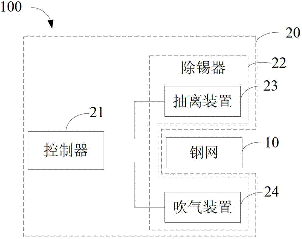
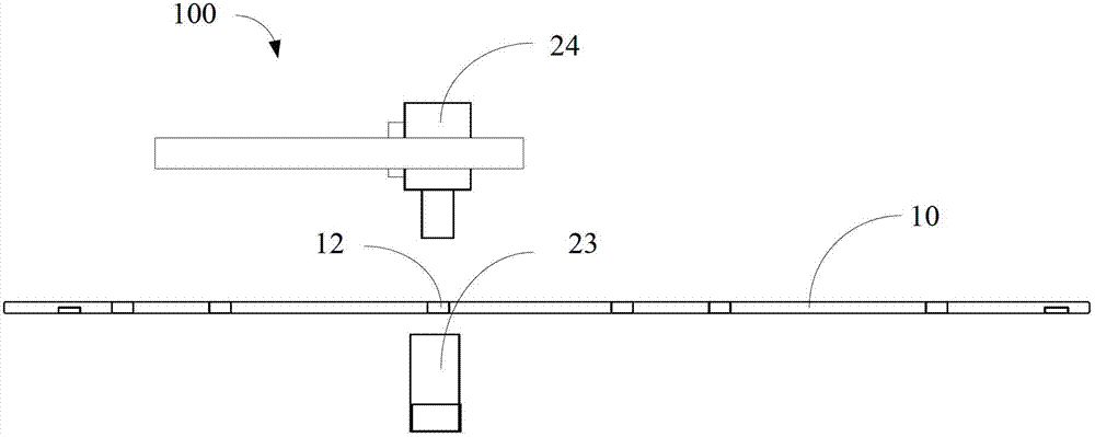
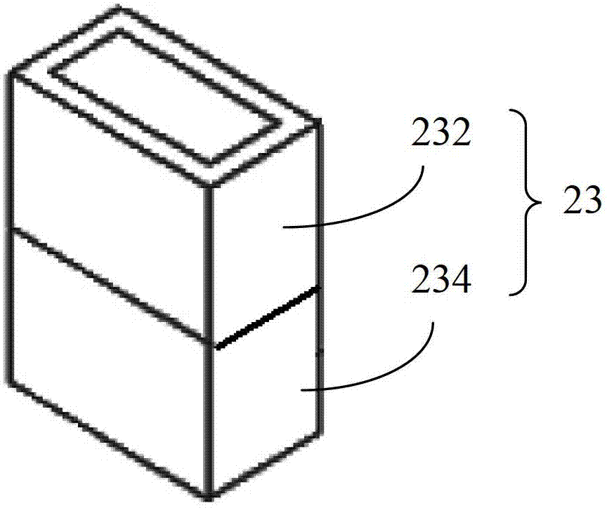
[0015] See figure 1 and 2 , a printing machine 100 provided in the first preferred embodiment of the present invention. The printing machine 100 includes a stencil 10 and a tin removal device 20 . The desoldering equipment 20 is used to remove the solder paste in the meshes of the stencil. The tin removal equipment 20 includes a controller 21 and a tin remover 22 . The controller 21 is connected to the tin remover 22 to control the tin remover 22 to move to the...


PUM


Abstract

The invention provides a tin-removing device used for removing the solder paste in the of a printing machine. The device is characterized in that the tin-removing device comprises a controller and a tin-removing machine, wherein the controller is connected to the tin-removing machine to control the tin-removing machine to move to the mesh of the steel mesh, so that the solder paste in the mesh can be separated from the mesh. According to the invention, removing the solder paste in the mesh conveniently and swiftly can be achieved without stopping production. The invention further provides a printing machine.

Description

technical field [0001] The invention relates to the field of electronic technology, in particular to a printing machine and tin removal equipment thereof. Background technique [0002] Typically, surface mount printers are used in the production of electronic devices. After the use of the surface mount printing machine, the stencil of the printing machine usually automatically cleans the back of the stencil of the printing machine by wiping paper. However, this cleaning method can only clean the back of the stencil, and the solder paste in the mesh holes of the stencil cannot be cleaned. To thoroughly clean the solder paste in the stencil mesh, the stencil needs to be disassembled and sent to the cleaning room for cleaning with ultrasonic equipment. But this cleaning method needs to disassemble the stencil, so production needs to be stopped. Contents of the invention [0003] The technical problem to be solved by the embodiments of the present invention is to provide a ...

Claims


Application Information

Patent Timeline
Patent Type & Authority Applications(China)
IPC IPC(8): B41F35/00
Inventor 白林周慧玲贺礼贤
Owner HUAWEI MACHINERY
Features
  • R&D
  • Intellectual Property
  • Life Sciences
  • Materials
  • Tech Scout
  • Unparalleled Data Quality
  • Higher Quality Content
  • 60% Fewer Hallucinations
Learn More