Eureka AIR delivers breakthrough ideas for toughest innovation challenges, trusted by R&D personnel around the world.

Textile flyings cleaner

A cleaner and flying flower technology, which is applied in textiles and papermaking, can solve the problems that the flying flowers on the traveler cannot be cleaned, and achieve the effects of improving service life, avoiding yarn breakage, and improving strength

Inactive Publication Date: 2013-07-17
TIANCHANG LIHENG TEXTILE MACHINERY CO LTD
View PDF7 Cites 3 Cited by
  • Summary
  • Abstract
  • Description
  • Claims
  • Application Information

AI Technical Summary

Problems solved by technology

During the assembly process, the traveler is installed on the top of the steel ring, the bottom plate is pressed against the bottom of the steel ring, and the cleaning plate is close to the traveler; when the traveler is running at high speed, when the flying flowers attached to the traveler hit the cleaning plate, The fly can be removed from the traveler, therefore, it cannot completely remove the fly from the traveler

Method used


Image

  • Textile flyings cleaner
  • Textile flyings cleaner
  • Textile flyings cleaner

Examples


Embodiment Construction

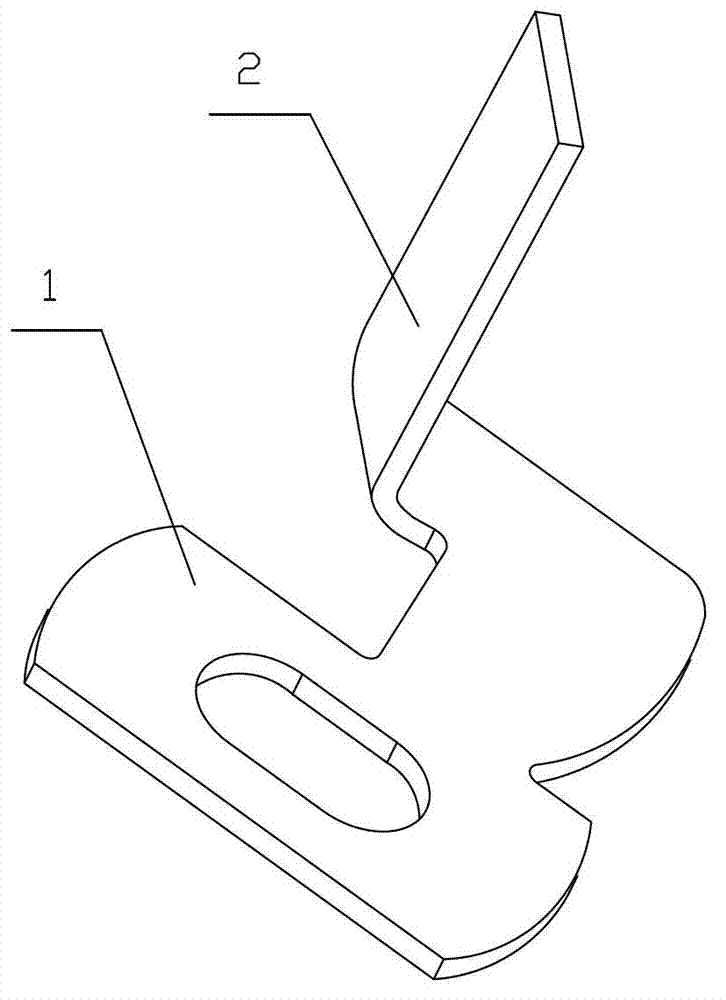
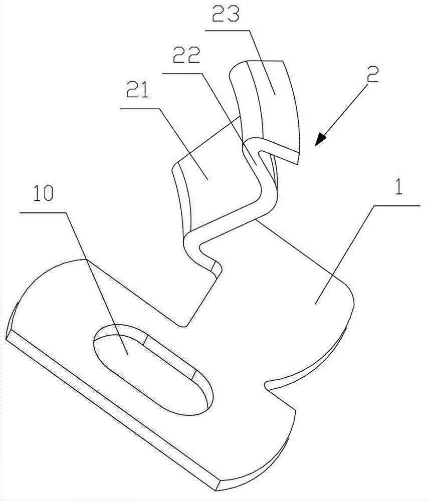
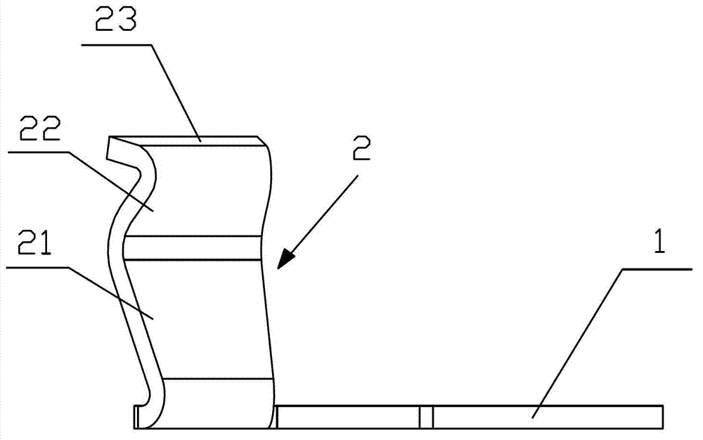
[0023] like figure 2 and image 3 as shown, figure 2 It is a perspective view of a textile fly cleaner proposed by the present invention, image 3 for figure 2 main view.

[0024] refer to figure 2 and image 3 , a textile fly cleaner proposed by the present invention, comprising a bottom plate 1 and a cleaning plate 2 extending upward from the bottom plate 1, and a mounting hole 10 is provided on the bottom plate 1; the cleaning plate 2 is bent laterally at a predetermined angle to form a first cleaning plate 21 and a second cleaning plate 22.

[0025] During the working process, the traveler is placed on the upper part of the steel ring, the base plate 1 is pressed against the lower part of the steel ring, and the traveler is close to the inside of the bending of the first cleaning plate 21 and the second cleaning plate 22. When the traveler is running at high speed, the An airflow is generated between the first cleaning plate 21 and the second cleaning plate 22, ...


PUM


Abstract

The invention discloses a textile flyings cleaner which comprises a bottom plate and a cleaning plate. The bottom plate extends upwardly to form the cleaning plate, and the cleaning plate is transversely bent to form a first cleaning plate and a second cleaning plate by a preset included angle. During high-speed rotation of a steel wire ring, air flow is generated between the first and second cleaning plates, so that flyings on the steel wire ring can be thoroughly cleaned under impact of the air flow. On one hand, breakage of yarns due to flyings is avoided; on the other hand, the rotation speed of the steel wire ring is unaffected by the flyings, and accordingly, the service life of the steel wire ring is prolonged. Furthermore, yarn quality is protected from being affected by the flyings, and yarn strength is improved.

Description

technical field [0001] The invention relates to the technical field of textiles, in particular to a textile fly cleaner. Background technique [0002] In the spinning process, in order to reduce the flying flowers attached to the traveler and reduce the yarn breakage caused by the flying flowers, generally, the flying flowers on the traveler are removed by setting a flying flower cleaner. [0003] like figure 1 Shown is a schematic structural view of a typical fly cleaner in the prior art. [0004] exist figure 1 Among them, the fly cleaner includes a base plate 1 and a cleaning plate 2 arranged on the base plate 1, and the cleaning plate 2 has a flat plate structure as a whole. During the assembly process, the traveler is installed on the top of the steel ring, the bottom plate is pressed against the bottom of the steel ring, and the cleaning plate is close to the traveler; when the traveler is running at high speed, when the flying flowers attached to the traveler hit t...

Claims


Application Information

Patent Timeline
Patent Type & Authority Applications(China)
IPC IPC(8): D01H11/00
Inventor 宋菊芳
Owner TIANCHANG LIHENG TEXTILE MACHINERY CO LTD
Why Eureka
Eureka Blog
Learn More