
Security smart lock

A smart lock and safe technology, applied in the field of security smart locks, can solve the problems that electronic seals cannot fully meet the requirements of the regulator's control, economic losses, oil, sludge and sand entering the charging hole, and achieve stable and reliable functions and simplified structure. , the effect of eliminating the possibility of cheating

Active Publication Date: 2016-09-28
南京三宝科技股份有限公司
View PDF6 Cites 1 Cited by
  • Summary
  • Abstract
  • Description
  • Claims
  • Application Information

AI Technical Summary

Problems solved by technology

[0002] In the current process of cargo transportation, in order to ensure the safety of goods in transit, mechanical seals are generally used to close container doors, compartment doors or valves, but mechanical seals are poor in safety and easy to imitate, while electronic seals with only detection functions cannot fully meet the supervision Party, especially customs, requirements for control
The security smart lock devices that have appeared in recent years generally have disadvantages such as complex structure, bulky size, cumbersome on-site operation, high failure rate, and easy cheating. Moreover, the current security smart locks must work together with mechanical locks with keys. Once lost or The situation of forgetting the key will seriously affect the use of the site, especially the logistics industry that has high requirements on timeliness, because the failure of the mechanical lock of the safety smart lock or the loss of the key will make it impossible to unload the goods, which will cause serious waste of time and huge economic losses.
In addition, the current security smart locks all use wired charging. During long-term use, the charging hole is prone to oil, sludge and sand, causing malfunctions.

Method used


Image

  • Security smart lock
  • Security smart lock
  • Security smart lock

Examples


Embodiment Construction

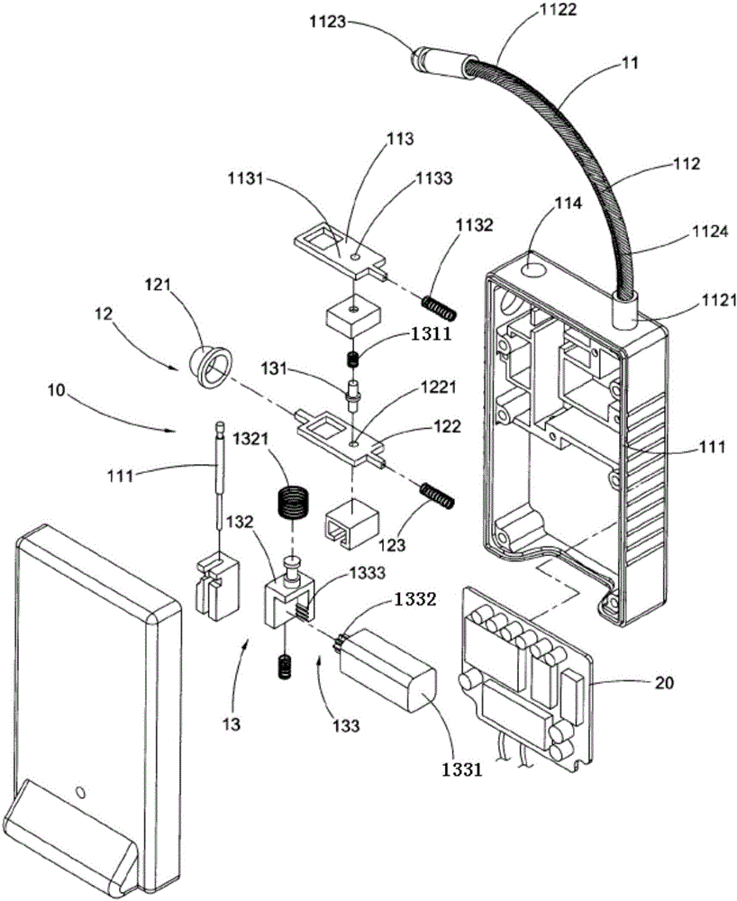
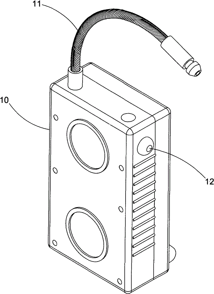
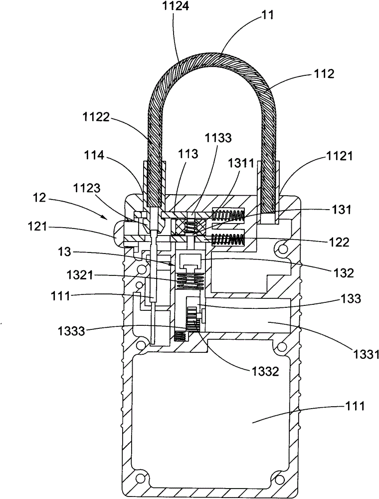
[0045] Such as Figure 1 to Figure 5 As shown, the security smart lock according to a preferred embodiment of the present invention includes a mechanical lock 10 and a wireless electronic lock 20, and is switched between a locked state and an unlocked state, thereby passing through the mechanical lock 10 It realizes dual lock control with the wireless electronic lock 20 to ensure the safe use of the safe smart lock.

[0046] The mechanical lock 10 includes a locking mechanism 11, an unlocking mechanism 12 and a control mechanism 13. The wireless electronic lock 20 includes a main control unit and a wireless communication unit; when the safety smart lock is in the locked state, the locking mechanism 11 is closed to realize the locking of the mechanical lock 10, so The wireless communication unit receives a lock command, the main control unit drives the control mechanism 13 to disengage from the locking mechanism 11, and the unlocking mechanism 12 cannot open the locking mechanism ...


PUM


Abstract

A safe smart lock comprises a mechanical lock and a wireless electronic lock. The mechanical lock comprises a locking mechanism, an unlocking mechanism and a control mechanism. The wireless electronic lock comprises a main control unit and a wireless communication unit. When the lock is locked, the locking mechanism is closed to achieve locking of the mechanical lock, the wireless communication unit receives a locking instruction, the main control unit drives the control mechanism to be separated from the locking mechanism, and the unlocking mechanism cannot unlock the locking mechanism; when the lock is unlocked, the wireless communication unit receives an unlocking instruction, the main control unit drives the control mechanism to be operably connected with the locking mechanism and the unlocking mechanism, and accordingly the unlocking mechanism unlocks the locking mechanism through the locking mechanism. According to the safe smart lock, control of the physical mechanical lock and the wireless electronic lock is achieved, the safe smart lock automatically gives an alarm in case of anomaly and can be monitored in real time, and people can timely know and adopt measures correspondingly when the safe smart lock is damaged or unlocked illegally.

Description

Technical field [0001] The invention relates to a safe intelligent lock, in particular to a safe intelligent lock that integrates a mechanical lock and an electronic lock and can be monitored in real time. Background technique [0002] In the current process of cargo transportation, in order to ensure the safety of the goods in transit, mechanical seals are generally used to close container doors, compartment doors or valves, but mechanical seals are poor in safety and easy to imitate, and electronic seals with only detection functions cannot fully meet supervision Party, especially the requirements of the customs on control strength. In recent years, the security smart lock equipment generally has the disadvantages of complex structure, large volume, cumbersome on-site operation, high failure rate, easy to cheat, etc., and the current security smart locks must work together with a mechanical lock with a key. Once lost or The situation of forgotten keys will seriously affect the...

Claims


Application Information

Patent Timeline
Patent Type & Authority Patents(China)
IPC IPC(8): E05B63/14E05B49/00E05B47/02E05B15/00E05B45/06
Inventor 刘岗
Owner 南京三宝科技股份有限公司
Learn More