Support frame

A support frame and support column technology, which is applied in the field of support frames, can solve the problems of the supported object rollover and support instability of the support frame, and achieve the effects of not being easy to rollover, conducive to precise operation, and high stability

Inactive Publication Date: 2013-07-17
KUN SHAN POWER STENCIL
View PDF13 Cites 8 Cited by
  • Summary
  • Abstract
  • Description
  • Claims
  • Application Information

AI Technical Summary

Problems solved by technology

[0011] The technical problem to be solved by the present invention is that the support frame in the prior art is unstable,

Method used


Image

  • Support frame
  • Support frame
  • Support frame

Examples


Embodiment 1

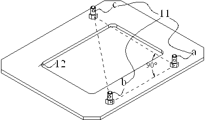
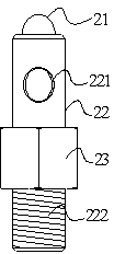
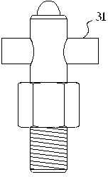
[0043] a support such as figure 1 As shown, it includes three support columns 11 and a substrate 12 for fixing the support columns; the support columns 11 are distributed on the abutment 12, and the positions of the three support columns form a right triangle; figure 2 Shown is a schematic diagram of the structure of the support column 11, which is inlaid by a spherical head 21 and a bar bar 22. A through hole 221 for adjustment is provided on the bar bar 22, and a threaded structure 222 is provided at the lower end of the bar bar 22. , the other bar area is provided with a nut 23 for loosening the support column; image 3 Shown is a structural schematic diagram of inserting the adjustment bar 31 in the support column; in order to improve the stability and practicability of the support frame, the support column 11 is made of wear-resistant stainless steel, and the abutment 12 for fixing the support column is made of light aluminum Made of alloy material.

[0044]

Embodiment 2

[0046] A support frame, including a support column and an abutment for fixing the support column, three support columns are distributed near the periphery of the abutment; the structure of the support column is the same as that of Embodiment 1, which is composed of a spherical structure and a cylindrical structure, and The materials are all made of hard wear-resistant stainless steel, and the hard abutment is made of light aluminum; there are threaded holes on the abutment corresponding to the threaded structure of the support column, and the support column is screwed and fixed on the support column through the thread structure. on the abutment. The points where the three support columns are located form the three vertices of the triangle, and the formed triangle is an isosceles acute triangle. Insert the adjustment bar into the support column.

[0047]

Embodiment 3

[0049] A support frame, including a support column and an abutment for fixing the support column, three support columns are distributed near the periphery of the abutment; other parts are similar to Embodiment 1, but the structure of the support column is composed of an elliptical structure and a cylinder Structural composition, the elliptical curved surface structure is the support part, and its material is made of hard wear-resistant stainless steel, the support column is fixed on the hard abutment by screwing, and the hard abutment is made of light aluminum material Obtained; the points where the three support columns are located form the three vertices of the triangle, and the formed triangle is a non-isosceles acute triangle, and the adjustment bar is inserted into the support columns.

[0050]


PUM


Abstract

The invention relates to a support frame, and mainly solves the problems in the prior art that the supporting of a support frame is not stable, and reproducibility of the planimetric position of an object arranged on an operating table is not good, so the precision operation is not facilitated, and the support frame is not easy to level. The invention adopts the technical scheme that the support frame is of a three-point orthogonal structure; the support frame comprises three supporting columns and a base for fixing the supporting columns; points of positions, at which the three supporting columns are arranged, are connected to form a triangle; the supporting columns are provided with circular through holes; and adjusting strips which are matched with the circular through holes are provided. The problems are well solved, and the support frame can be applied to the industrial production of the support frame and a support platform for the precision operation.

Description

technical field [0001] The invention relates to a support frame. Background technique [0002] From the era of human beings, manufacturing began to appear. At first, they only made some simple tools. Until the formation of tribal civilization, people were able to make more sophisticated tools. After the industrial revolution began, machinery developed rapidly, especially after the second industrial revolution, the vigorous development of the manufacturing industry made people's requirements for the quality of life continuously improved, and various mechanical instruments began to be manufactured. These instruments were initially only used in life. Until the late 1950s, people began to apply it to quantify industrial production and improve the precision of production design. With the development and improvement of mechanical instruments, the words of precision instruments began to appear in people's eyes in the early 1960s. Since then, precision instruments have continued...

Claims


Application Information

Patent Timeline
IPC IPC(8): F16M11/22
Inventor 魏志凌高小平潘世珎
Owner KUN SHAN POWER STENCIL
Why Eureka
Try Eureka