Rehabilitation training device for hemiplegia patients
A technology for rehabilitation training and patients, which is applied in the field of medical devices and can solve problems such as training that cannot simulate normal walking
- Summary
- Abstract
- Description
- Claims
- Application Information
AI Technical Summary
Problems solved by technology
Method used
Image
Examples
Embodiment 1
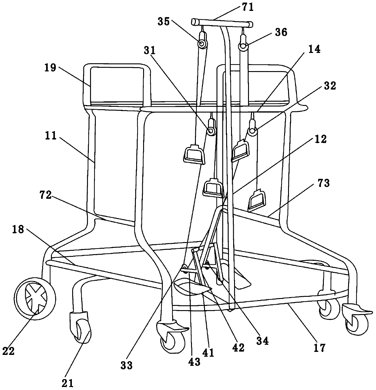
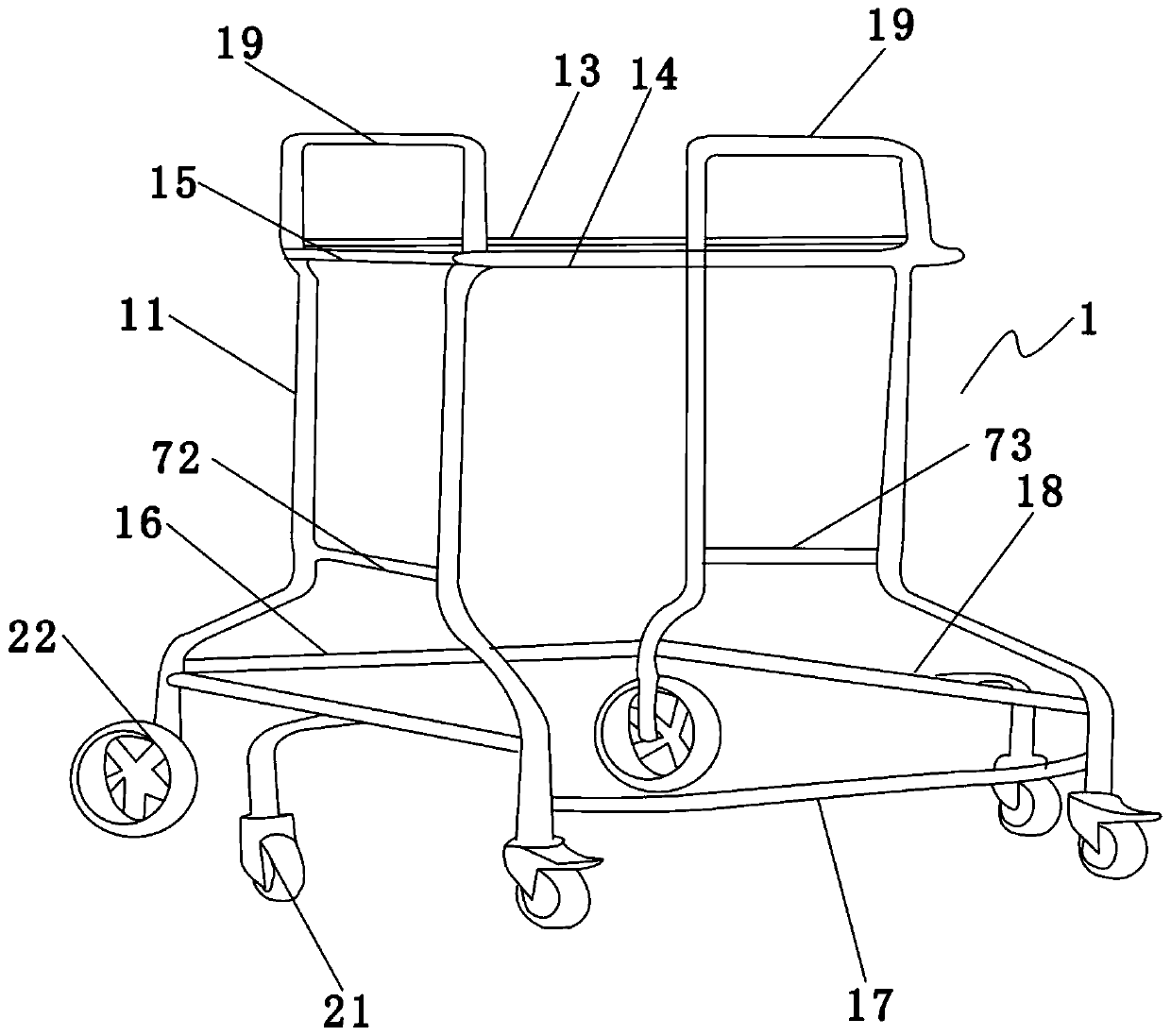
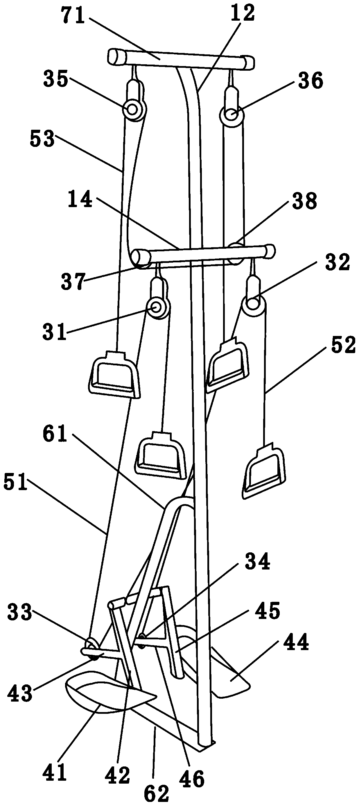
[0056] like figure 1 As shown, a rehabilitation training device for hemiplegic patients comprises a vehicle frame 1, a seat plate and casters. The front crossbar 13, the first rear crossbar 14 and the first side crossbars 15 on the left and right sides are composed, the casters are fixed on the bottom of the vehicle frame 1, and the seat plate is clamped with the vehicle frame 1 ; Also includes a pulley assembly and a pedal assembly located below the pulley assembly, the pedal assembly includes a left pedal assembly, a right pedal assembly and a main connecting rod, and the left pedal assembly and the right pedal assembly are respectively located at the main connecting rod The left and right sides of the rod are connected with the main connecting rod shaft, and the second vertical rod 12 is fixed on the middle part of the first rear cross bar 14, and the main connecting rod is fixed on the second vertical rod 12 The pulley assembly includes a vertical first pulley 31 and a se...
Embodiment 2
[0063] The difference between this embodiment and embodiment 1 is:
[0064] The second vertical bar 12 extends upward beyond the height of the vehicle frame 1, and the top end of the second vertical bar 12 is provided with a third cross bar 71, and the pulley assembly also includes a The vertical fifth pulley 35 and the sixth pulley 36 at the left and right ends, and the seventh horizontal pulley 37 and the eighth pulley 38 on the left and right ends of the first rear cross bar 14, the third connecting rope 53 passes through the fifth pulley 35, the seventh pulley 37, the eighth pulley 38 and the sixth pulley 36 in turn and connects the four.
[0065] By adopting the above-mentioned technical scheme, the patient exerts a downward force on the fifth pulley 35, and the force is transmitted to the transverse seventh pulley 37 through the third connecting rope 53, and the seventh pulley 37 changes the direction of the force, so that the downward force Then, under the action of th...
Embodiment 3
[0067] The difference between this embodiment and embodiment 2 is:
[0068] like image 3 and Figure 4 As shown, the vehicle frame 1 also includes a second front cross bar 16 and a second rear cross bar 17 connecting the bottom of the first vertical bar 11, and the left and right sides connecting the bottom of the first vertical bar 11 The second side cross bar 18, the second vertical bar 12 is fixedly connected with the second rear cross bar 17.
[0069] By adopting the above technical solution, the second front cross bar 16, the second rear cross bar 17 and the second side cross bar 18 are arranged at the bottom of the vehicle frame 1, which increases the weight of the bottom of the vehicle frame 1 and makes the vehicle frame 1 difficult to move forward. Tilting, also difficult for rollover, the upper end of the second vertical bar 12 is fixed with the first rear cross bar 14, the lower end is fixed with the second rear cross bar 17, and the second vertical bar 12 is fixe...
PUM
 Abstract
Description
Claims
Application Information
 - R&D
- Intellectual Property
- Life Sciences
- Materials
- Tech Scout
- Unparalleled Data Quality
- Higher Quality Content
- 60% Fewer Hallucinations
Browse by: Latest US Patents, China's latest patents, Technical Efficacy Thesaurus, Application Domain, Technology Topic, Popular Technical Reports.
© 2025 PatSnap. All rights reserved.Legal|Privacy policy|Modern Slavery Act Transparency Statement|Sitemap|About US| Contact US: help@patsnap.com


