
Flexible micro rail transporter and using method thereof

A technology of transportation device and micro-rail, which is applied in the direction of transportation and packaging, conveyors, mechanical conveyors, etc., can solve the problems of poor passability of trolleys, difficulty in laying out rail trolley tracks, and laborious pulling and delivery of goods, etc., to achieve occupancy The effect of small space, overall light weight, and easy entry and storage

Pending Publication Date: 2019-10-15
GUANGXI ZHUANG AUTONOMOUS REGION ACAD OF AGRI SCI
View PDF0 Cites 4 Cited by
  • Summary
  • Abstract
  • Description
  • Claims
  • Application Information

AI Technical Summary

Problems solved by technology

[0005] The purpose of the present invention is to provide a flexible micro-rail transportation device and its use method, to solve the technical problems of poor passability of trolleys in the prior art and laborious pulling and delivery of goods; Layout Difficult Questions

Method used


Image

  • Flexible micro rail transporter and using method thereof
  • Flexible micro rail transporter and using method thereof
  • Flexible micro rail transporter and using method thereof

Examples


Embodiment 1

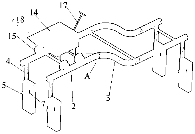
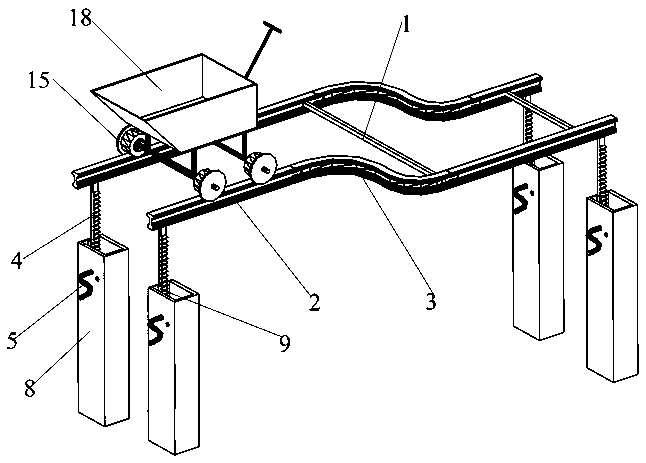
[0041] A flexible micro-rail transportation device, such as figure 1 As shown, it includes a transportation track, an adjustable support supporting the transportation track, and a cargo trolley 18 placed on the transportation track; the transportation track includes two parallel steel tracks, and a first connecting support 1 is provided between the steel tracks. It includes a straight track unit 2 and a curved track unit 3. The adjacent straight track units 2 and the adjacent straight track units 2 and the curved track units 3 are fixed by splicing components, such as image 3 As shown, the splicing component is a tenon-and-mortise structure; the adjustable support includes several height-adjustable support units, the height-adjustable support unit includes a rack 4, a rotating handle 5, a gear 6, a clamp 7 and a sleeve 8, and a rack 4 The top is supported under the transportation track, and the lower part is built into the sleeve 8. One end of the rotating handle 5 is fixed to t...

Embodiment 2

[0043] In the first embodiment, the cross section of the sleeve 8 is square, and the width of the inner wall of the sleeve 8 to which the rack 4 abuts is adapted to the width of the rack 4. The second embodiment is based on the first embodiment. figure 2 It can be seen that the width of the sleeve 8 is greater than the width of the rack 4, the inner wall of the sleeve 8 is provided with baffles 9 on both sides of the rack 4, and the space between the two baffles 9 is the running channel of the rack 4.

Embodiment 3

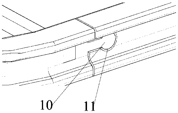
[0045] On the basis of the first embodiment, the tenon-and-mortise structure includes a protrusion 10 and a groove 11 respectively provided on adjacent rail units. The protrusion 10 includes a head and a neck. The shape of the groove 11 is similar to that of the protrusion. The shape of the part 10 is adapted, the cross section of the head is a circular structure, and the diameter of the circular structure is larger than the maximum width of the neck, such as Figure 7~9 As shown, the cross-section of the head is rectangular, trapezoidal, inverted trapezoid and arrow-shaped. The arrow shape is not shown. The width of the neck is the same as the length of the shortest bottom side of the trapezoid or inverted trapezoid. The bottom surface of the steel track is provided with teeth for securing The square steel 16 of the strip 4, for ease of production, the straight track unit 2 and the curved track unit 3 are made of square steel. Each curved track unit 3 includes a curved section ...


PUM


Abstract

The invention discloses a flexible micro rail transporter and a using method thereof. The flexible micro rail transporter comprises a transporting rail, an adjustable support for supporting the transporting rail, and a freight trolley placed on the transporting rail, wherein the transporting rail comprises two parallel steel rails; each of the steel rails comprises a straight rail unit and a bentrail unit; every two adjacent straight rail units are fixed through a splicing component; the straight rail unit and the bent rail unit adjacent to each other are fixed through the splicing component;the splicing components are mortise and tenon joint structure; the adjustable support comprises a plurality of height adjustable support units; each of the height adjustable support units comprises arack, a rotary handle, a gear in meshing transmission connection with the rack, a fastener and a sleeve; the top of the rack supports the lower part of the transporting rail; the lower part of the rack is arranged in the sleeve; one end of the rotary handle is fixed with the gear; and the other end of the rotary handle is exposed to the outer side of the sleeve. The flexible micro rail transporter has modular design, and is reasonable in structure, light in overall structure, small in occupied area and easy to manufacture, mount and dismantle.

Description

Technical field [0001] The invention relates to the field of cargo transportation, in particular to a flexible micro-rail transportation device and a method of use thereof. Background technique [0002] As a short-line cargo transportation tool, the trolley is mainly pulled or pushed by manpower. Due to its simple structure, low cost and wide range of use, it will be very difficult to pull or push when it encounters thresholds or uneven ground transportation surfaces, especially When crossing the threshold, it needs to be pressed down or lifted hard to turn over. While turning over with wedge-shaped stakes is a little labor-saving, it is still laborious and easy to roll over when there are more goods. [0003] The transportation trolley is mainly driven by the front of the vehicle or the cable pulling method. Due to its simple structure, it has a wide range of use. However, the transportation trolley often causes the transportation trolley to tip over in the courtyard or the uneven...

Claims


Application Information

Patent Timeline
Patent Type & Authority Applications(China)
IPC IPC(8): B65G35/00
CPCB65G35/00
Inventor 邢钇浩温东强覃初贤覃欣广蒋文艳李果果赵洪涛望飞勇邓立宝黄超岑信成谭祥武颜福建
Owner GUANGXI ZHUANG AUTONOMOUS REGION ACAD OF AGRI SCI
Learn More