System and method for monitoring in real time the operating state of an IGBT device

一种器件、温和的技术,应用在用直接对热敏感的电/磁性元件的温度计、单个半导体器件测试、半导体/固态器件测试/测量等方向,能够解决不适合IGBT结温在线测量等问题

Active Publication Date: 2013-07-17
ABB (SCHWEIZ) AG
View PDF5 Cites 44 Cited by
  • Summary
  • Abstract
  • Description
  • Claims
  • Application Information

AI Technical Summary

Problems solved by technology

Therefore, these techniques are not suitable for in-line measurement of IGBT junction temperature especially if the timely resolution should be at a frequency close to the control frequency of the IGBT device

Method used


Image

  • System and method for monitoring in real time the operating state of an IGBT device
  • System and method for monitoring in real time the operating state of an IGBT device
  • System and method for monitoring in real time the operating state of an IGBT device

Examples


Embodiment Construction

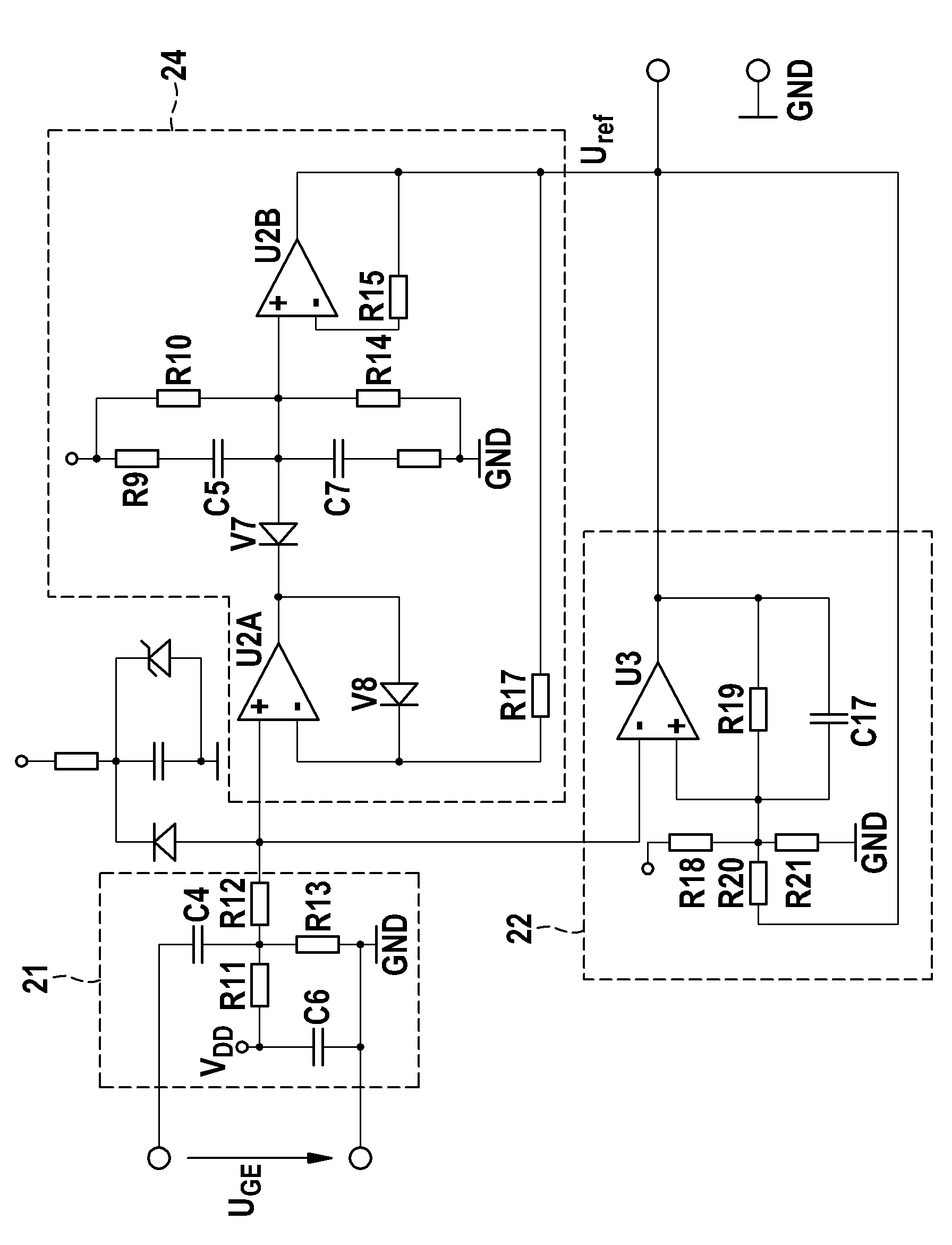
[0034] Figure 1 shows a diagram for supplying from a high supply potential at V H with a low supply potential V L A schematic diagram of the three-phase output IGBT driver module 1 generated between applied DC supply sources. The IGBT driver module 1 is controlled by a control unit 2 . The IGBT driver module 1 comprises a B6 circuit with three half-bridges 11, one for each output phase U, V, W.

[0035] Each half-bridge 11 is at high supply potential V H with a low supply potential V L A series connection between the two IGBT devices. In each of the half bridges 11, the controller terminal C of the first IGBT device 12 is connected to the high supply potential V H , while the emitter terminal E of the first IGBT device 12 is connected to the output nodes of the corresponding output phases U, V, W. The collector terminal C of the second IGBT device 13 is connected to this output node and the emitter terminal E of the first IGBT device 12, while the collector terminal C of...


PUM


Abstract

The present invention relates to a system for monitoring in real time the operating state of an IGBT device, in particular for determining a junction temperature and / or a remaining lifetime of an IGBT device, comprising: -a differential unit for receiving a gate-emitter voltage characteristic of the IGBT device to be measured and for differentiating the gate-emitter voltage characteristic to obtain pulses correlating with edges formed by a Miller plateau phase during a switch-off phase of the IGBT device; -a timer unit for measuring the time delay between the obtained pulses indicating the start and end of the Miller plateau phase during the switch-off phase of the IGBT device; -a junction temperature calculation unit for determining the junction temperature and / or the remaining lifetime of the IGBT device based on the measured time delay.

Description

technical field [0001] The present invention relates to the field of IGBT devices, in particular to a method for measuring or estimating the junction temperature of an IGBT device. Background technique [0002] The junction temperature of an IGBT device in a semiconductor module during operation is an important parameter, eg in power electronic converters, which provides information about the thermal stress to which the device is exposed. Therefore, it can be used to predict and evaluate the aging of IGBT devices and power modules and estimate the remaining lifetime of IGBT devices. [0003] Conventionally, the junction temperature of an IGBT device is measured using standard temperature measurement techniques, such as probing with an infrared camera, a thermocouple inside the IGBT device package directly at or near the IGBT semiconductor, or measuring the internal gate resistance of the IGBT device in order to obtain a temperature indication. These techniques either invol...

Claims


Application Information

Patent Timeline
Patent Type & Authority Applications(China)
IPC IPC(8): G01R31/26
CPCH03K17/18G01K7/01G01R31/2619G01K2217/00G01R31/2642H01L22/30H03K2017/0806G01R31/26
Inventor V.孙达拉莫尔蒂A.海内曼E.比安达F.泽弗卢G.克纳普I.尼斯托尔R.布洛赫
Owner ABB (SCHWEIZ) AG
Why Eureka
Try Eureka