
Broadband target direction finding method based on two-dimensional frequency domain sparse constraint

A two-dimensional frequency domain, sparsely constrained technology, applied in the field of communication, can solve problems such as the influence of estimation accuracy errors, and achieve high resolution, outstanding angle detection effect, and accurate angle detection effect

Inactive Publication Date: 2013-07-17
XIDIAN UNIV
View PDF4 Cites 18 Cited by
  • Summary
  • Abstract
  • Description
  • Claims
  • Application Information

AI Technical Summary

Problems solved by technology

The disadvantage of this method is that it needs to construct the focusing matrix and perform angle pre-estimation, and the estimation accuracy is easily affected by the pre-estimation error.

Method used


Image

  • Broadband target direction finding method based on two-dimensional frequency domain sparse constraint
  • Broadband target direction finding method based on two-dimensional frequency domain sparse constraint
  • Broadband target direction finding method based on two-dimensional frequency domain sparse constraint

Examples


Embodiment Construction

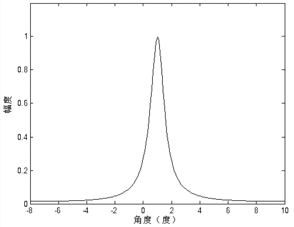
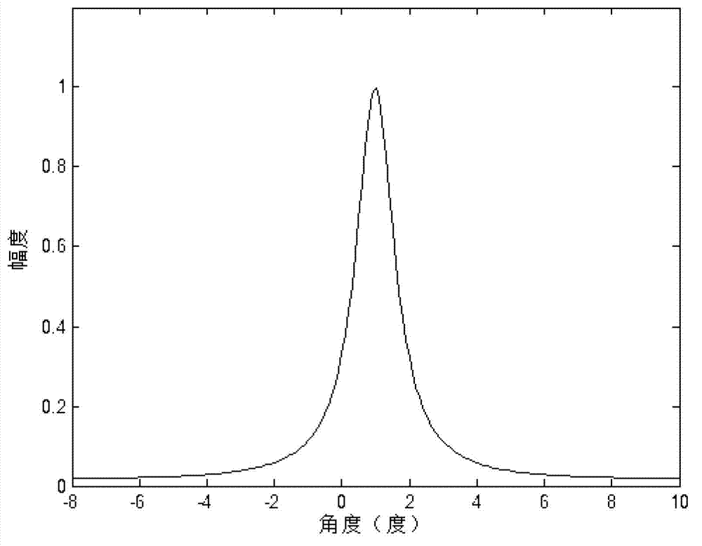
[0036] The present invention will be described in further detail below in conjunction with the accompanying drawings.

[0037] refer to figure 1 , the specific implementation steps of the present invention are as follows:

[0038] Step 1: Obtain the target reflection signal received by the mth array element.

[0039] Assuming that the broadband signal transmitted by the radar is s(t), the relative time delay of signal propagation caused by the distance between the i-th target and the m-th array element is τ mi , the target reflected signal received by the mth array element is:

[0040] x m ( t ) = Σ i = 1 N s ( t - τ mi ) + n m ...


PUM


Abstract

The invention discloses a broadband target direction finding method based on two-dimensional frequency domain sparse constraint. The method mainly solves the problems of a low angle resolution ratio, the poor coherent signal source estimation accuracy and a large calculation amount of common algorithms of prior methods. The technical scheme includes that the method comprises the steps of fully using target space sparseness and priori knowledge of array element receiving signals in a two-dimensional domain, and performing two-dimensional domain projection conversion on the array element receiving signals to obtain a two-dimensional projection spectrum; performing angle division on the angle measuring range, and designing a sparse base of the two-dimensional projection spectrum; solving an optimization problem through an optimization solving algorithm to obtain a high-resolution angle spectrum; and performing peak value detection on the angle spectrum through a threshold comparison method to obtain a target angle value. The broadband target direction finding method has the advantages of being small in calculation amount, high in measuring accuracy and angle resolution ratio and applicable to target angle estimation of radars and sonars.

Description

technical field [0001] The invention belongs to the technical field of communication, and further relates to a wideband target direction finding method based on two-dimensional frequency domain sparse constraints in the field of array signal processing, which can be used for target angle estimation of radar and sonar. Background technique [0002] The phased array is an array antenna that uses the coherence principle of electromagnetic waves to control the phase of the current fed to each radiating array element through a computer, thereby changing the beam direction. The traditional method of adjusting the beam pointing based on the mechanical scanning structure cannot adapt to the real-time detection task of high maneuvering targets due to the low rotation frequency and slow data update. Phased array antenna adopts electronic scanning method, which can realize real-time update of echo data, so it has gained wide attention. Among them, the use of phased array angle measure...

Claims


Application Information

Patent Timeline
IPC IPC(8): G01S3/00
Inventor 赵光辉刘自成王学磊石光明沈方芳
Owner XIDIAN UNIV
Learn More