a slide deck

A technology for a wafer stage and a chip is applied in the field of plasma technology to meet the requirements of maintaining vacuum degree, avoid process unevenness, and simplify the effect of uniform gas structure.

Active Publication Date: 2015-10-28
INST OF MICROELECTRONICS CHINESE ACAD OF SCI
View PDF3 Cites 0 Cited by
  • Summary
  • Abstract
  • Description
  • Claims
  • Application Information

AI Technical Summary

Problems solved by technology

[0004] In order to solve the above problems, the present invention proposes a loading table capable of improving the uniformity and stability of the plasma process technology, optimizing the plasma chip fixing structure, and reducing the specific unevenness of the plasma electromagnetic field.

Method used


Image

  • a slide deck
  • a slide deck
  • a slide deck

Examples


Embodiment Construction

[0029] In order to deeply understand the present invention, the present invention will be described in detail below in conjunction with the accompanying drawings and specific embodiments.

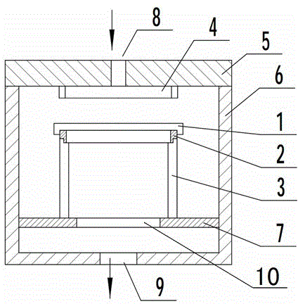
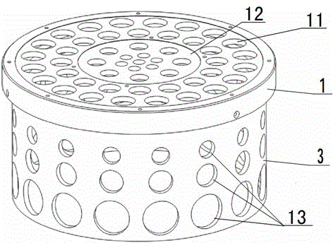
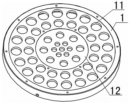
[0030] See attached figure 1 The slide table provided by the present invention includes a chamber 6 , a chamber upper cover 5 , electrodes 4 , a chip fixing plate 1 , a fixing plate support ring 3 and a support plate 7 , and an air outlet 9 is opened at the bottom of the chamber 6 . The chamber upper cover 5 is installed on the chamber 6 , and the chamber upper cover 5 is provided with an air inlet 8 , and the chamber upper cover 5 is attached with an electrode 4 at the lower part of the air inlet 8 . The support disc 7 is annular, and the center of the support disc 7 is provided with a first through hole 10 , and the support disc 7 is installed on the inner side wall of the chamber 6 . The support ring 3 of the fixed disc is installed on the support disc 7 , and the support ring 3 of the ...


PUM


Abstract

The invention discloses a chip carrier and belongs to the technical field of plasma body processes. The chip carrier comprises a cavity, a cavity upper cover, an electrode, a chip fixing disc, a fixing disc supporting ring and a supporting disc. A chip fixing structure of the chip carrier comprises the chip fixing disc and the fixing disc supporting ring. An unevenness phenomenon caused by an asymmetric structure when a plasma body is started can be reduced or avoided, and a gas homogenizing structure is simplified. Under the starting condition of the plasma body, the chip carrier does not cause a gas escape phenomenon, so that the requirement of a chip for the cavity vacuum degree can be kept.

Description

technical field [0001] The invention relates to the technical field of plasma technology, in particular to a chip carrier for supporting chips. Background technique [0002] The carrier stage used in the plasma etching process is a chip fixing structure, and choosing a reasonable chip fixing structure plays an important role in the reliability and stability of the plasma etching process. When selecting the chip fixing structure, factors such as the size of the chip, the gas flow distribution of the etching process, the physical and chemical influence of the chip fixing structure material on the etching process, and the thermal effect generated by the etching process should be considered. For the process structure with radio frequency or DC bias, when selecting the chip fixing structure, the influence of the electrode on the electromagnetic field distribution of the loading stage should also be considered. [0003] In the prior art, the slide stage is usually made of anodize...

Claims


Application Information

Patent Timeline
Patent Type & Authority Patents(China)
IPC IPC(8): H01J37/32H01J37/20H01L21/67H01L21/683
Inventor 席峰李楠李勇滔张庆钊夏洋
Owner INST OF MICROELECTRONICS CHINESE ACAD OF SCI
Why Eureka
Try Eureka