Forming a structural laminate that resists stress

a structural laminate and stress-resistant technology, applied in the field of printing structural elements, can solve the problems of restricting the freedom of box designers to adjust the mechanical characteristics of the box, affecting the quality of corrugated boards, and inability to provide relative strength configurations in conventional ways of making corrugated boards, etc., to achieve control of tensile strength and bending moment, less expensive, and the effect of reducing the number o

Active Publication Date: 2016-02-02
EASTMAN KODAK CO
View PDF26 Cites 0 Cited by
  • Summary
  • Abstract
  • Description
  • Claims
  • Application Information

AI Technical Summary

Benefits of technology

[0018]An advantage of this invention is that it provides a structural laminate or element that can be readily produced and that provides improved mechanical properties in a desired area of the structure. Toner is used to adhere the sheets together. A smaller mass of toner than of some other adhesives can be used to adhere the sheets together, reducing mass and weight of the structure. Since toner is used, the sheets do not have to be pressed so tightly together during bonding that there is a risk of squeezing the adhesive out. This is an advantage over glue.
[0026]In various embodiments, multiple toner regions are used to control tensile strength and bending moment independently. Unlike glue, the size (thickness), contents (additives), and position of toner patterns can be readily controlled. Moreover, stiffness varies as the square of the second moment of inertia, or as thickness4. The direction of stiffness can be controlled by selecting an appropriate toner pattern. Unlike prior schemes using toner as an adhesive between surfaces substantially in contact with each other, various embodiments described herein use toner to hold sheets in relationship to each other, with a gap between them. Toner can provide tall structures with low mass, no outgassing, and strength along any number of axes. Conventional corrugated board has high mass and provides strength only along one axis or very few axes (e.g., two: tensile with the flutes, and normal to the board). Foaming posterboard outgasses, so it requires more care in handling during production. In various embodiments, a single layer of toner is used on the sheet rather than multiple layers. This improves productivity of the printer producing the structures. In various embodiments, the toner is a weather-resistant source of strength for wet paper, e.g., lawn signs.

Problems solved by technology

However, all conventional fluted cardboard has certain mechanical properties in certain dimensions, and those properties cannot readily be adjusted depending on the type of product to be packaged.
This restricts the box designer's freedom to adjust the mechanical characteristics of the box based on its intended use.
This relative strength configuration cannot be provided by conventional ways of making corrugated board, or by ways of making extruded plastic corrugations such as COROPLAST.
Extra space in each box is filled with packing materials that add additional weight and cost.
In addition, maintaining inventory of the packaging materials and boxes cost money and takes up space.
Moreover, the adhesives used in corrugated-box manufacturing have deficiencies.
Epoxy, glue and hot-melt glue change volume when they cool, producing internal stresses that can weaken the board.

Method used


Image

  • Forming a structural laminate that resists stress
  • Forming a structural laminate that resists stress
  • Forming a structural laminate that resists stress

Examples


Embodiment Construction

[0053]As used herein, the terms “receiver,”“receivers,”“medium,”“media,”“recording medium,” and “recording media” are used interchangeably. “Sheet” and “web” receivers are used interchangeably except when discussing embodiments that are particularly adapted to use one of those styles of receiver. “Adhere” is used herein both intransitively (toner adheres to paper) and transitively (toner adheres two sheets to each other, i.e., the adhesive forces between a toner mass and each of two sheets holds those two sheets together).

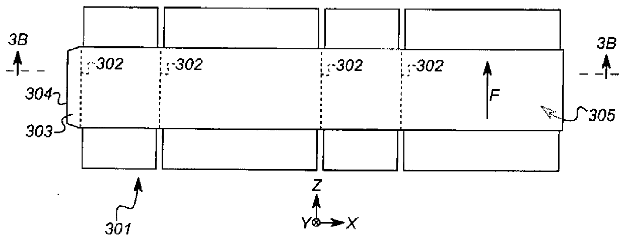
[0054]Referring back to FIG. 3B, the direction F of extension of flutes 306 is the direction in which a ray extended in direction F will not cross fluted sheet 312, even if extended to the edge of box blank 301. In conventional corrugated board, such as that shown here, the opposite to direction F can also be considered the direction of extension of flutes 306, since either direction F or its opposite can be extended to the edges of box blank 301 without crossing f...


PUM

PropertyMeasurementUnit
Young's modulusaaaaaaaaaa
volume-weighted median diameteraaaaaaaaaa

Abstract

A structural laminate having a selected resistance to a first stress applied in a selected first stress direction relative to the laminate is formed from first and second sheets. A selected volume of toner is deposited on the first sheet to form a deposited toner pattern, the deposited toner pattern being disposed over a selected first surface area of the first sheet and extending normal to the first sheet by a selected first height. The second sheet, or toner thereon, is brought into contact with the deposited toner pattern. The deposited toner pattern is fixed to produce a fixed toner pattern that adheres the second sheet to the first sheet, in that way forming the laminate. The fixed toner pattern includes one or more first contiguous regions of toner extending in a direction within about 45° of the stress direction, so that the contiguous regions resist the applied stress.

Description

CROSS-REFERENCE TO RELATED APPLICATIONS[0001]This application claims priority of provisional Patent Application No. 61,640,914(now 13 / 663,522, U.S. Publication No. 2013 / 0292030), filed May 1, 2012.[0002]This application is co-filed with and has related subject matter to U.S. patent application No. 61 / 640,909(now 13 / 663,514, U.S. Publication No. 2013 / 0292053), filed May 1, 2012, titled “FORMING A STRUCTURAL LAMINATE,” and U.S. patent application No. 61 / 640,929(now 13 / 663,529, U.S. Publication No. 2013 / 0292049), filed May 1, 2012, titled “FORMING A 3D STRUCTURAL LAMINATE,” each of which is incorporated herein by reference in its entirety.FIELD OF THE INVENTION[0003]This invention pertains to the field of printed manufacturing and more particularly to printing structural elements.BACKGROUND OF THE INVENTION[0004]Corrugated cardboard or fiberboard is widely used to package goods for transit. An outer sheet of liner (or “linerboard”) is glued to a fluted sheet to provide stiffness in the...

Claims


Application Information

Patent Timeline
Patent Type & Authority Patents(United States)
IPC IPC(8): B29C65/78B31B1/00B32B38/14B32B37/14B32B37/10B32B37/12B32B37/18C09J9/00
CPCB32B37/1292B31B1/00B31B2201/88B31B2201/95B31B2203/084B31B2217/0084B31B2217/084B32B2307/718B32B2309/02B32B2309/105B32B2310/0831B32B2317/127Y10T156/10Y10T156/1737Y10T156/1741B31B50/006B31B50/88B31B2100/0024B31B2105/001B31B2105/0024
Inventor SCHINDLER, II, ROLAND, R.
Owner EASTMAN KODAK CO
Why Eureka
Try Eureka