
Plate electrode fixing structure

A fixed structure, flat electrode technology, applied in circuits, discharge tubes, electrical components, etc., can solve the problem of uneven plasma, achieve the requirements of wide uniformity distribution, maintain vacuum degree, and good uniformity effect.

Active Publication Date: 2013-06-05
INST OF MICROELECTRONICS CHINESE ACAD OF SCI
View PDF3 Cites 0 Cited by
  • Summary
  • Abstract
  • Description
  • Claims
  • Application Information

AI Technical Summary

Problems solved by technology

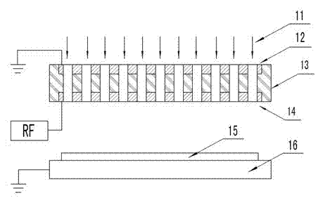
[0003] In order to solve the problem of the existing plasma electrode being fixed in the middle of the chamber and the uneven plasma caused by the fixing structure, the present invention provides a flat electrode fixing structure, including an insulating support on which a plurality of gas inlets are arranged. hole, the upper electrode and the lower electrode are evenly distributed around the air inlet hole; the upper electrode is fixed in the middle of the plasma chamber through the insulating support, and the reaction gas enters the plasma chamber through the air inlet hole, and the lower electrode RF power is applied, the upper electrode is grounded

Method used


Image

  • Plate electrode fixing structure
  • Plate electrode fixing structure

Examples


Embodiment Construction

[0015] The technical solutions of the present invention will be further described below in conjunction with the accompanying drawings and embodiments.

[0016] Such as figure 2 As shown, the embodiment of the present invention provides a flat electrode fixing structure, including an insulating support 13, on which a plurality of air inlet holes are arranged, and upper electrodes 12 and lower electrodes 14 are evenly distributed around the air inlet holes. The upper electrode 12 and the lower electrode 14 are metal electrodes, and the material of the metal electrodes can be but not limited to graphite, molybdenum, galvanized aluminum, stainless steel, aluminum alloy or oxygen-free copper. The thickness of the insulating support 13 is 5-1000mm. The insulating support 13 is made of insulating material, which can be but not limited to ceramics, quartz, polytetrafluoro or polycarbonate and the like. The frequency of the radio frequency power applied between the upper electrode 1...


PUM


Abstract

The invention discloses a plate electrode fixing structure, belonging to the technical field of plasma etching. The plate electrode fixing structure comprises an insulating support, the insulating support is provided with a plurality of air inlets, and upper electrodes and lower electrodes are arranged around the air inlets. The insulating support is 5-1,000mm thick and is made of an insulating material such as ceramic, quartz, polytetrafluoroethylene or polycarbonate. The frequency of a radio-frequency power supply applied between the upper electrodes and the lower electrodes is 0-10GHz. Thedistance between the upper electrodes and the lower electrodes is 2-1,000mm. the area diameter of the upper electrodes and the lower electrodes is 20-3,000mm. By adopting the plate electrode fixing structure, the scope of uniform distribution of a plasma starter can be widened, and particularly good edge uniformity can be achieved. When the plasma starter is used, no air discharging can be causedby the plate electrode fixing structure, and a vacuum chamber can meet vacuum requirements.

Description

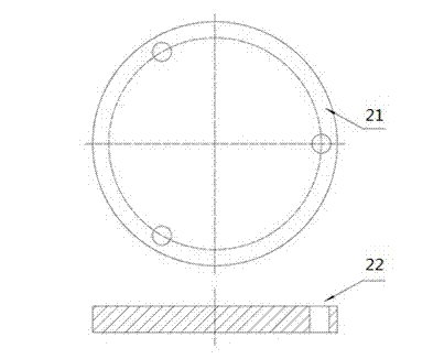
technical field [0001] The invention relates to the technical field of plasma etching, in particular to a flat electrode fixing structure. Background technique [0002] The electrodes used in the plasma etching process have various forms, and choosing a reasonable and reliable electrode fixing form plays an important role in the stability of the plasma process. The plate electrode is a commonly used electrode form in processes such as plasma etching and deposition. The plate electrode 21 adopts such as figure 1 The peripheral multi-point method shown is fixed, and the flat plate electrode 21 is suspended on the upper end of the process chamber through the electrode fixing peripheral hole 22 through bolts, and this method cannot be fixed in the middle of the chamber, and cannot meet certain process requirements. This electrode fixing structure is prone to plasma inhomogeneity at the edge of the bolt fixing peripheral hole, and the field symmetry of the physical properties of...

Claims


Application Information

Patent Timeline
Patent Type & Authority Patents(China)
IPC IPC(8): H01J37/32
Inventor 席峰李勇滔李楠张庆钊夏洋
Owner INST OF MICROELECTRONICS CHINESE ACAD OF SCI
Learn More