Energy-reducing device for high-energy particles and its preparation method

A high-energy particle and energy-reducing technology, which is applied in radiation/particle treatment, ion implantation plating, nuclear engineering, etc., can solve the problems of toxicity, difficulty in popularization and application, and high price, and achieve good stability, convenient use, The effect of simple structure

Active Publication Date: 2019-05-31
HEFEI INSTITUTES OF PHYSICAL SCIENCE - CHINESE ACAD OF SCI
View PDF2 Cites 0 Cited by
  • Summary
  • Abstract
  • Description
  • Claims
  • Application Information

AI Technical Summary

Problems solved by technology

However, although the beryllium material of the energy reducer in this system has the advantage of good stability under the particle beam, it is expensive and toxic, so it is very difficult to popularize and apply

Method used


Image

  • Energy-reducing device for high-energy particles and its preparation method
  • Energy-reducing device for high-energy particles and its preparation method
  • Energy-reducing device for high-energy particles and its preparation method

Examples


Embodiment 1

[0035] The concrete steps of preparation are:

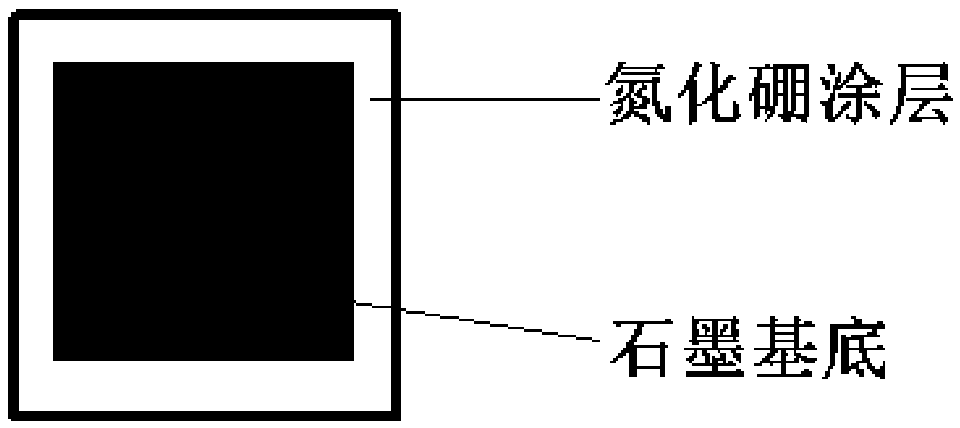
[0036] Step 1, first place the graphite substrate in a vacuum chamber. Then, according to the volume ratio of ammonia gas, boron chloride gas and nitrogen gas at a ratio of 0.8:1.2:40, the three gases are mixed to obtain a mixed gas.

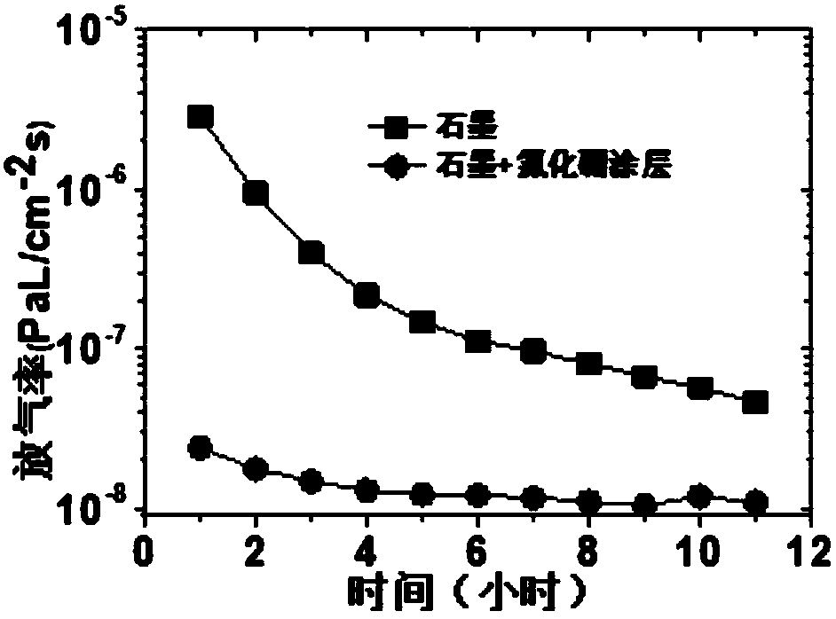
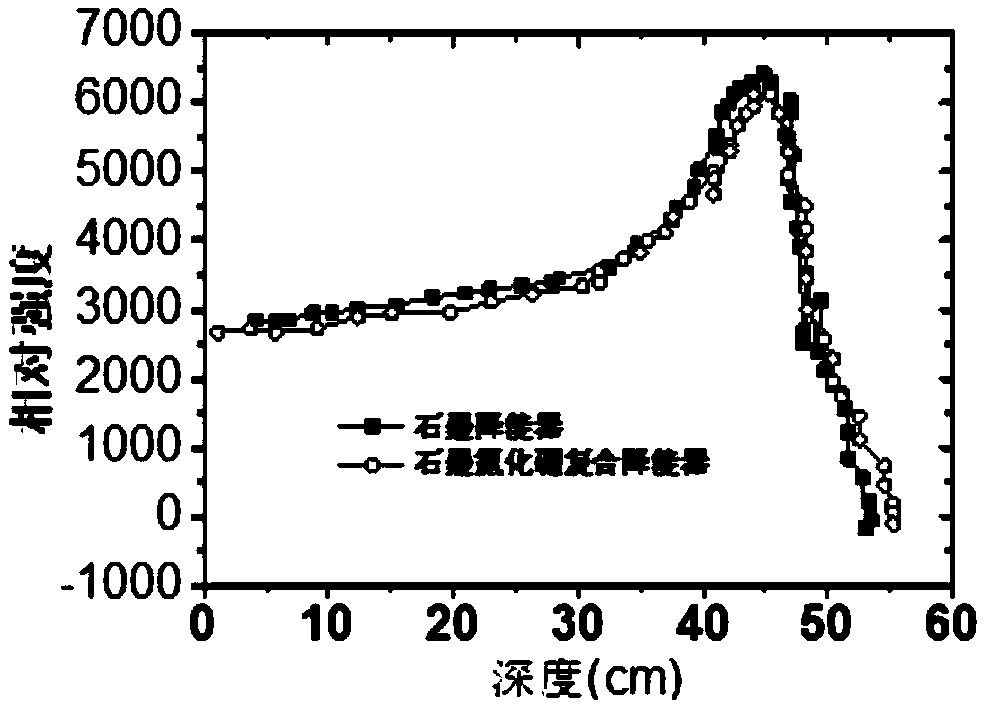
[0037] Step 2, firstly raise the temperature in the vacuum chamber to 500°C. Feed flow into the vacuum chamber again and be the mixed gas 36h of 10sccm, make such as figure 1 shown, and as figure 2 and image 3 The high-energy particle de-energy device shown in the curve in .

Embodiment 2

[0039] The concrete steps of preparation are:

[0040] Step 1, first place the graphite substrate in a vacuum chamber. Then, according to the volume ratio of ammonia gas, boron chloride gas and nitrogen gas at a ratio of 0.9:1.1:45, the three gases are mixed to obtain a mixed gas.

[0041] Step 2, first raise the temperature in the vacuum chamber to 875°C. Feed flow into the vacuum chamber again and be the mixed gas 30h of 32.5sccm, make such as figure 1 shown, and as figure 2 and image 3 The high-energy particle de-energy device shown in the curve in .

Embodiment 3

[0043] The concrete steps of preparation are:

[0044] Step 1, first place the graphite substrate in a vacuum chamber. Then, according to the volume ratio of ammonia gas, boron chloride gas and nitrogen gas at a ratio of 1:1:50, the three gases are mixed to obtain a mixed gas.

[0045] Step 2, first raise the temperature in the vacuum chamber to 1250°C. Pass into the vacuum chamber again and flow is the mixed gas 24h of 55sccm, makes such as figure 1 shown, and as figure 2 and image 3 The high-energy particle de-energy device shown in the curve in .


PUM

PropertyMeasurementUnit
thicknessaaaaaaaaaa

Abstract

The invention discloses a high-energy particle energy-reducing device and a preparation method thereof. The energy-reducing device is a graphite substrate covered with a dense boron nitride coating, and the thickness of the dense boron nitride coating is 5-800[mu]m; the preparation method adopts a vapor deposition method, and comprises the following steps: firstly, placing a graphite substrate into a vacuum chamber, then mixing an ammonia gas, a boron chloride gas and a nitrogen gas according to the volume ratio of the ammonia gas to the boron chloride gas to the nitrogen gas of (0.8-1.2):(0.8-1.2):(40-60) to obtain a mixed gas, then firstly raising the temperature in the vacuum chamber to 500-2000 DEG C, and finally introducing the mixed gas with a flow quantity of 10-100sccm into the vacuum chamber for 12-36h to obtain the target product. According to the high-energy particle energy-reducing device provided by the invention, the degassing rate is much lower than that of a graphite energy-reducing device, a high-energy particle beam has good penetrating performance on the high-energy particle energy-reducing device and the graphite energy-reducing device, and the high-energy particle energy-reducing device can be easily, widely and commercially applied to the fields of high-precision and high-energy particle beam energy reduction of a cyclotron.

Description

technical field [0001] The invention relates to an energy-reducing device and a preparation method thereof, in particular to a high-energy particle energy-reducing device and a preparation method thereof. Background technique [0002] Based on the fixed energy of the particle beam generated by the cyclotron, in some specific applications, it is required to quickly change the energy of the outgoing particle beam, so it is necessary to configure a particle energy-reducing device in the front of the cyclotron with fixed energy. The setting of the particle energy reduction device is based on the principle of the interaction between the high-energy particle beam and the matter. When the particle beam is irradiated on the object, the energy is mainly lost through the process of ionization and excitation. The mass radiation stopping power is expressed, and the calculation formulas are as follows: [0003] [0004] [0005] According to formulas (1) and (2), when selecting ma...

Claims


Application Information

Patent Timeline
Patent Type & Authority Patents(China)
IPC IPC(8): G21K1/10C23C14/06C23C16/34
CPCC23C14/0647C23C16/342G21K1/10
Inventor 李新化刘敏史同飞马文霞
Owner HEFEI INSTITUTES OF PHYSICAL SCIENCE - CHINESE ACAD OF SCI
Why Eureka
Try Eureka