Illumination device and method for producing an illumination device

A technology for light-emitting devices and light-emitting areas, which is applied in the parts of lighting devices, semiconductor devices of light-emitting elements, lighting devices, etc., can solve problems such as loss of clarity and loss, and achieve the effect of increasing light output.

Inactive Publication Date: 2013-07-17
OSRAM GMBH
View PDF7 Cites 5 Cited by
  • Summary
  • Abstract
  • Description
  • Claims
  • Application Information

AI Technical Summary

Problems solved by technology

However, the diffuser only enables light diffusion over a limited angle, and in addition a part of the light incident into the diffuser is lost because it is reflected bac...

Method used


Image

  • Illumination device and method for producing an illumination device
  • Illumination device and method for producing an illumination device
  • Illumination device and method for producing an illumination device

Examples


Embodiment Construction

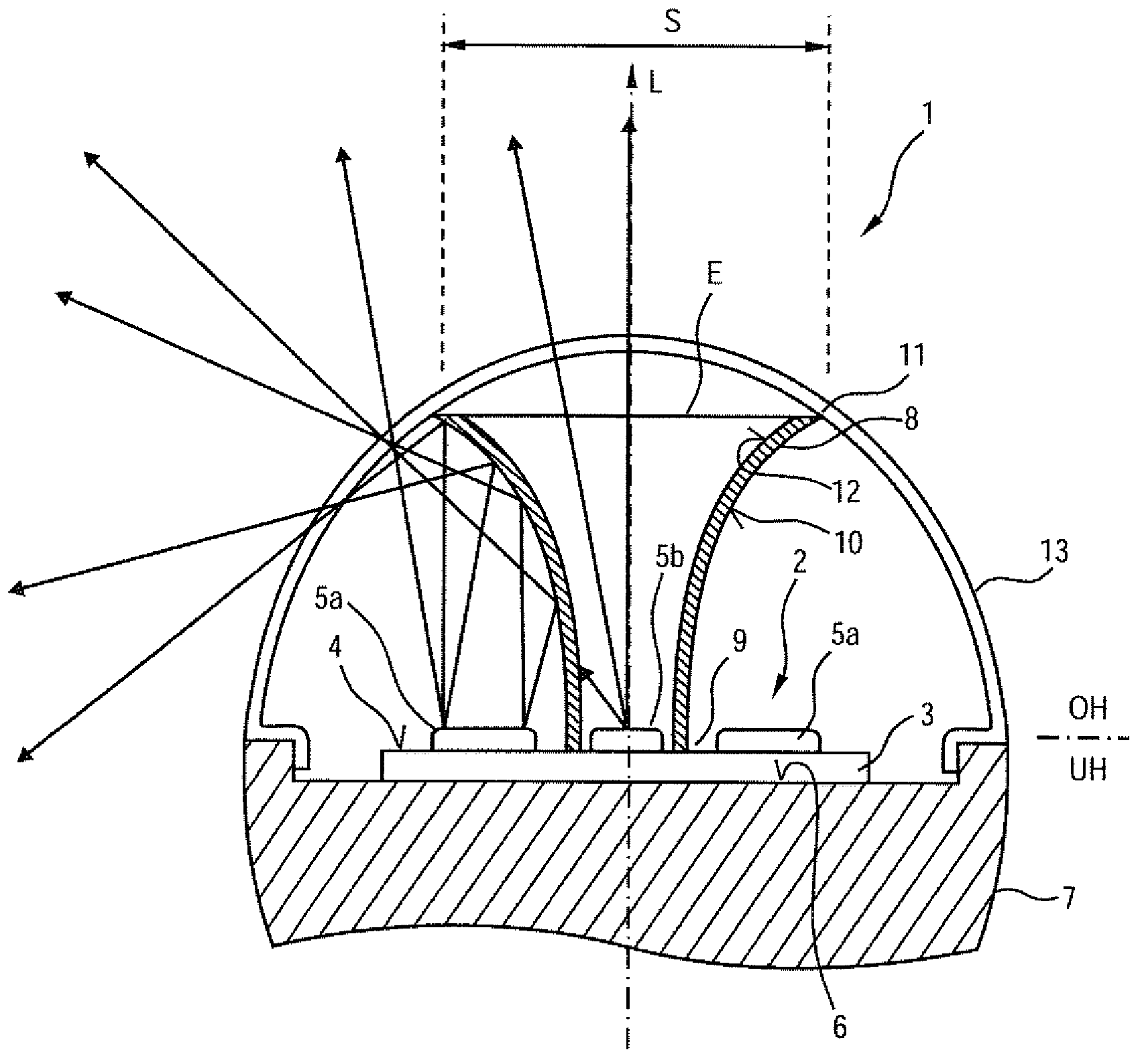
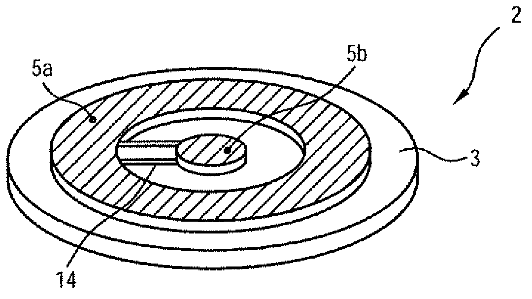
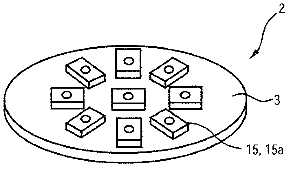
[0058] figure 1 A partial view of the front of the lighting device 1 according to the invention in the form of an incandescent retrofit lamp is shown as a sectional view in side view. The lighting device 1 is designed substantially rotationally symmetrically with respect to the longitudinal axis L. As shown in FIG. The luminous device 1 has a light-generating unit 2, wherein the light-generating unit 2 has a substrate 3, on the front side 4 of which points in the direction of the longitudinal axis L, two luminous regions 5a, 5b, ie the annular outer A light-emitting area 5a and a circular inner light-emitting area 5b. The two luminous regions 5a, 5b are separated from each other by an annular gap.

[0059] The base plate 3 is fastened with its back side 6 in a thermally conductive manner to the front side of the heat sink 7 . The rear side (not shown) of the heat sink 7 can be turned into the base for electrical and mechanical connection to a suitable lamp holder.

[0060]...


PUM


Abstract

The invention relates to an illumination device (1) comprising at least one reflector (8) and at least one light generating unit (2), wherein the reflector (8) is designed to and arranged for reflecting at least a portion of the light emitted by the at least one light generating unit into a spatial region (UH) that cannot be directly illuminated by said light generating unit, and the at least one light generating unit (2) comprises at least one lighting region (5a, 5b) having an emission characteristic that is substantially uniform in a circumferential direction of the illumination device (1). The invention further relates to a method for producing an illumination device according to claim 12, wherein the method comprises at least the following steps: forming a bulb (49) which comprises an opening (50) at the tip (51) thereof, and which is in particular shaped as a conic segment, so that said bulb curves inward in the region of the tip (51) thereof; mirroring the bulb (49) at least in a region of the tip (51) thereof; and closing off the opening (50).

Description

technical field [0001] The invention relates to a lighting device with a reflector and at least one light generating unit. The invention also relates to a method for producing a corresponding lighting device. Background technique [0002] Especially in LED incandescent retrofit lamps which are designed to replace conventional incandescent lamps and which use light-emitting diodes as light sources, it is desirable that the light beams radiate into as large a solid angle area as possible. Diffusers are mostly used for this purpose. However, the diffuser only enables light diffusion over a limited angle, and in addition a part of the light incident into the diffuser is lost because it is reflected back, for example, on the inner side of the diffuser and is partly reabsorbed by the surface or by the LED itself, And the light emitted by the light emitting device loses clarity. Contents of the invention [0003] It is an object of the present invention to provide a lighting d...

Claims


Application Information

Patent Timeline
IPC IPC(8): F21K99/00
CPCF21K9/00F21K9/135F21Y2101/02F21V7/04F21Y2103/022F21K9/50F21V3/02F21V7/048F21V7/06F21V7/07F21V23/002F21K9/232F21K9/60F21Y2103/33F21Y2115/10F21Y2115/15F21V3/10F21K9/68
Inventor 法比安·雷因格鲁贝尔妮科尔·布雷德纳塞尔
Owner OSRAM GMBH
Why Eureka
Try Eureka