Automatic feeding and discharging mechanism of engraving and milling machine and feeding and discharging method

A technology of automatic loading and unloading, fine carving machine, applied in the field of fine carving machine, to achieve the effect of reasonable structure design, high efficiency and simple operation

Active Publication Date: 2013-07-24
SHENZHEN YUANYANG XIANGRUI MACHINERY
View PDF7 Cites 15 Cited by
  • Summary
  • Abstract
  • Description
  • Claims
  • Application Information

AI Technical Summary

Problems solved by technology

[0003] The object of the present invention is to provide an automatic loading and unloading mechanism and a loading and unloading method of Jingdiao Machine, w

Method used


Image

  • Automatic feeding and discharging mechanism of engraving and milling machine and feeding and discharging method

Examples


Embodiment 1

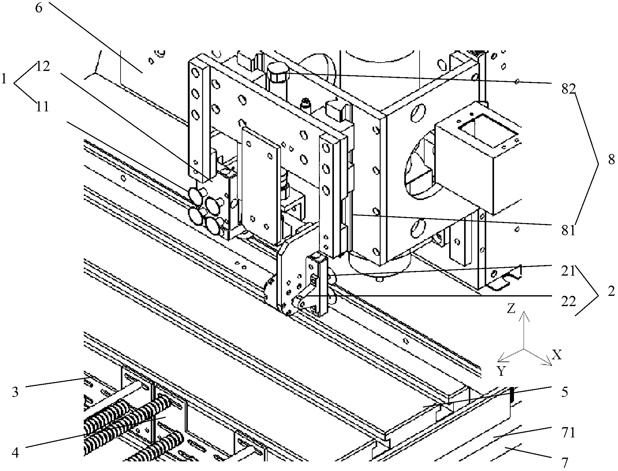
[0029] like figure 1 An automatic loading and unloading mechanism of the engraving machine shown in Embodiment 1, including a retrieving component 1, a discharging component 2, a loading frame 3, a unloading frame 4, a positioning fixture, a workbench 5, and an X-axis displacement structure 6 , Y-axis displacement structure 7 and Z-axis displacement structure 8. The loading frame 3 and the blanking frame 4 are placed side by side on the workbench 5, the positioning jig is placed on the workbench, and the positioning jig is located on one side of the loading frame and the unloading frame; the Z-axis displacement structure 8 is set on the X axis displacement structure 6, and the Z-axis displacement structure 8 is displaced along the X-axis direction; the reclaiming assembly 1 and the discharging assembly 2 are arranged on the Z-axis displacement structure 8, and the reclaiming assembly 1 and the discharging assembly 2 are arranged along the Z-axis Axial displacement; the workbe...

Embodiment 2

[0038] Embodiment 2 discloses the loading and unloading method used in Embodiment 1, including:

[0039] a. Both the loading frame 3 and the blanking frame 4 are installed on the workbench 5, and the distance between the loading frame 3 and the blanking frame 4 is adjusted so that the distance is the same as the distance between the feeding assembly 1 and the discharging assembly 2 basically the same;

[0040] b. When starting processing, the glass to be processed is installed in the loading frame 3, the blanking frame 4 is an empty box, and the workbench 5 moves back and forth along the Y axis with the loading frame 3; the suction cup 11 moves along the X axis. The axial direction moves to the position matched with the loading frame 3; at the same time, the retrieving suction cup 11 turns over 90 degrees and faces the workbench 5, and the Z-axis driving device 82 starts to work at the position where the first piece of glass is expected to be taken, so that the retrieving suct...


PUM


Abstract

The invention discloses an automatic feeding and discharging mechanism of an engraving and milling machine and a feeding and discharging method. The automatic feeding and discharging mechanism of the engraving and milling machine comprises a taking assembly, a placing assembly, a feeding frame, a discharging frame, a positioning jig, a worktable, an X-axis displacement structure, a Y-axis displacement structure and a Z-axis displacement structure, wherein the feeding frame and the discharging frame are arranged on the worktable in parallel, the positioning jig is arranged on the worktable and is positioned at one sides of the feeding frame and the discharging frame, the Z-axis displacement structure is arranged on the X-axis displacement structure and moves in the X-axis direction, the taking assembly and the placing assembly are arranged on the Z-axis displacement structure and move in the Z-axis direction, and the worktable is arranged on the Y-axis displacement structure and moves in the Y-axis direction. By adopting the structure, the automatic feeding and discharging function of the engraving and milling machine is realized, the problem of automatic feeding and discharging during the glass processing is solved, and the automatic feeding and discharging mechanism has the advantages that the implementation method is simple, the efficiency is higher, and the positioning precision is high.

Description

technical field [0001] The invention relates to the field of fine carving machines, in particular to an automatic loading and unloading mechanism and a loading and unloading method of the fine carving machines. Background technique [0002] At present, the loading and unloading of the existing Jingdiao machine for processing glass generally adopts manual loading and unloading, and a few automatic loading and unloading mechanisms have complicated implementation methods and structures, low efficiency and low precision, which is not conducive to production. Contents of the invention [0003] The purpose of the present invention is to provide an automatic loading and unloading mechanism and method for Jingdiao Machine, which can solve the problem of automatic loading and unloading during glass processing, and facilitate the realization of an automated factory and reduce labor. [0004] To achieve the above object, the present invention adopts the following technical solutions:...

Claims


Application Information

Patent Timeline
IPC IPC(8): B44B1/06
Inventor 龚伦勇
Owner SHENZHEN YUANYANG XIANGRUI MACHINERY
Why Eureka
Try Eureka