Method and device for detecting balance point of balance weight of portal crane

A technology of counterweight balance and point detection, applied in cranes, transportation and packaging, load hanging components, etc., can solve the problems of heavy workload, heavy boom, severe vibration of the whole machine, etc., to achieve easy operation, eliminate safety The effect of hidden danger and error avoidance

Inactive Publication Date: 2015-02-25
HANGZHOU HUAXIN MECHANICAL & ELECTRICAL ENGINEERING CO LTD
View PDF4 Cites 0 Cited by
  • Summary
  • Abstract
  • Description
  • Claims
  • Application Information

AI Technical Summary

Problems solved by technology

However, this detection method is cumbersome to operate and needs to search for all points in the full range, and the workload is large. In addition, this detection method is dangerous. Due to the heavy weight of the boom, the whole machine vibrates violently when the brake of the luffing motor falls, causing damage to the door machine. Negative Effects

Method used


Image

  • Method and device for detecting balance point of balance weight of portal crane
  • Method and device for detecting balance point of balance weight of portal crane
  • Method and device for detecting balance point of balance weight of portal crane

Examples


Embodiment 1

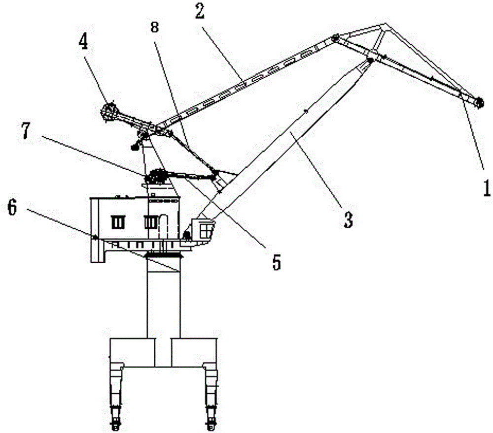
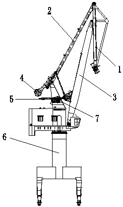
[0026] see figure 1 and figure 2 , In this embodiment, the door machine includes a base 6, a rack 5, a counterweight 4, a jib and a luffing motor 7.

[0027] In this embodiment, the jib includes an elephant trunk beam 1, an upper string frame 2 and a lower string frame 3, and the upper string frame 2 and the lower string frame 3 are both movably connected with the elephant trunk beam 1, and the upper string frame 2 and the lower string frame 3 are all movably connected on the abutment 6 . One end of the rack 5 is connected to the lower string frame 3, and the rack 5 is driven by the luffing motor 7.

[0028] In this embodiment, the balance point detection device for the counterweight 4 of the door machine includes a PLC, a frequency converter, a luffing motor 7 , a counterweight 4 , a jib and a base 6 .

[0029] In this embodiment, the PLC and the frequency converter communicate through the field bus, the frequency converter is electrically connected to the luffing motor 7...

Embodiment 2

[0040] In this embodiment, the method for detecting the balance point of the counterweight of the door machine includes the following steps.

[0041] 1) When the door operator is in the no-load state, control the arm frame of the door operator to shrink inward to the minimum position; start timing, and it is 0ms at this time.

[0042] 2) Control the outward movement of the jib at a constant speed; the speed is controlled at 5 m / min.

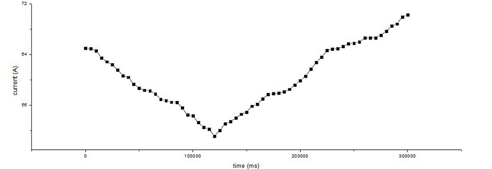
[0043] 3) Record the current value of the luffing motor 7 every 500 milliseconds; get Table 2.

[0044] Table 2: Current recording table.

[0045] time (ms) Current (A) 0 55.00 5000 55.34 10000 55.45 15000 55.51 20000 56.05 25000 56.96 30000 57.31 35000 58.12 40000 58.32 45000 58.50 50000 58.86 55000 59.56 60000 59.57 65000 60.20 70000 60.43 75000 60.80 80000 61.10 85000 61.27 90000 61.47 95000 62.08 100000 62.26 105000 62.66...

Embodiment 3

[0049] In this embodiment, the method for detecting the balance point of the counterweight of the door machine includes the following steps.

[0050] 1) When the door operator is in an unloaded state, control the arm frame of the door operator to shrink inward to the minimum position; start timing.

[0051] 2) Control the outward movement of the jib at a constant speed; the speed is controlled at 5 m / min.

[0052] 3) Record the current value of the luffing motor 7 every 500 milliseconds; get Table 3.

[0053] Table 3: Current recording table.

[0054] time (ms) Current (A) 0 80.00 5000 79.96 10000 79.76 15000 79.74 20000 79.37 25000 78.98 30000 78.96 35000 78.51 40000 78.10 45000 77.86 50000 77.44 55000 77.24 60000 77.08 65000 76.81 70000 76.33 75000 76.07 80000 75.80 85000 75.55 90000 75.24 95000 74.95 100000 74.64 105000 74.55 110000 74.20 11500...


PUM


Abstract

The invention relates to a method for detecting a balance point of a balance weight of a portal crane. The method comprises the following steps of: 1. controlling a cantilever crane of the portal crane to inwards contract to a minimum position under a no-load state; 2. controlling the cantilever crane to outwards move at a constant speed; 3. recording the current of an amplitude-variable motor; 4. drawing a curve by using time as a horizontal coordinate and the current of the amplitude-variable motor as a longitudinal coordinate; and 5. if the curve increases or reduces in a monotone manner, indicating that the balance point does not exist, and if the curve has a minimal value, indicating that the balance point exists. The method has the advantages of being accurate without errors, convenient to operate and complete in electric control, avoiding errors caused by manual operation, accurately locating the balance point, and eliminating potential safety hazards caused by the conventional mode.

Description

technical field [0001] The invention relates to a method for detecting the counterweight balance point of a gantry crane and a detection device for the counterweight balance point of a gantry crane, belonging to a quality detection method and device for a gantry crane. Background technique [0002] The portal crane refers to the portal crane, and the general portal crane needs to be equipped with a counterweight to balance the self-weight of the jib. When debugging the door operator, it is necessary to check whether the design of the counterweight of the door operator is reasonable. Before the production of the door operator, the designer will calculate the weight of the counterweight according to the mechanical calculation. The weight of the counterweight may not meet the requirements in practice. In the process of debugging the door operator, it is necessary to check whether the counterweight is reasonable, and the basis for checking whether the counterweight is reasonabl...

Claims


Application Information

Patent Timeline
Patent Type & Authority Patents(China)
IPC IPC(8): B66C13/16B66C23/74
Inventor 孟祥华刘春华邹新文陶杨军项建荣钟达王定华
Owner HANGZHOU HUAXIN MECHANICAL & ELECTRICAL ENGINEERING CO LTD
Why Eureka
Try Eureka