Gasifier

A technology of grate and solid processing equipment, applied in the field of gasifier, can solve the problems of no disclosure of scraper design and the like

Inactive Publication Date: 2013-07-24
SASOL TEKHNOLODZHI PROPRIEHJTEHRI LTD
View PDF19 Cites 2 Cited by
  • Summary
  • Abstract
  • Description
  • Claims
  • Application Information

AI Technical Summary

Problems solved by technology

Design aspects of the scraper are not disclosed in EP0159420

Method used


Image

  • Gasifier
  • Gasifier
  • Gasifier

Examples


Embodiment Construction

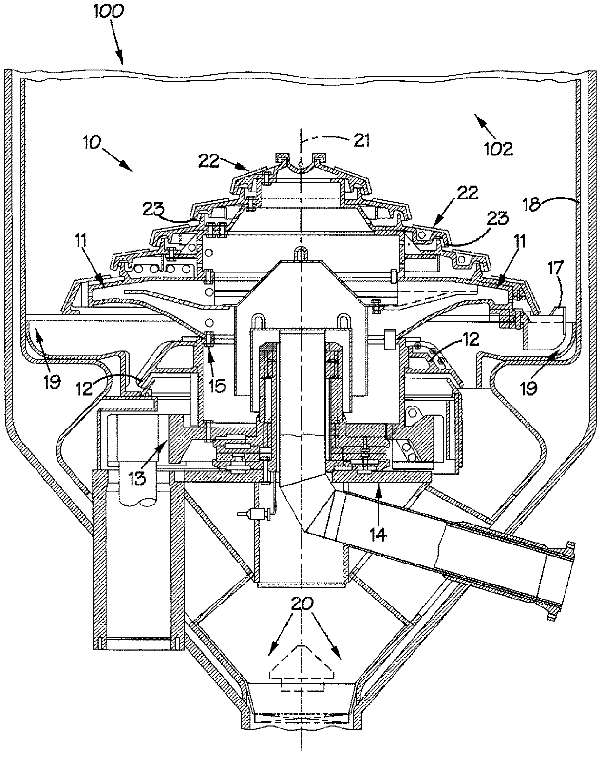
[0072] with reference to the attached figure 1 , reference numeral 10 generally designates a grate assembly 10 installed in a gasification vessel 100 of a fixed bed type dry bottom coal gasification furnace. The gasification vessel 100 defines a gasification chamber 102 (pressure vessel) within which the grate assembly 10 is positioned. The gasification chamber 102 has a wall 18 .

[0073] The grate assembly 10 includes a rotatable upper grate member 11 connected to a rotatable lower support structure 12 by a plurality of attachment bolts 15 . The rotatable lower support structure 12 is drivingly connected to a ring gear 13 which in turn is connected via a gearbox to an electric motor (not shown). In use, the electric motor and gearbox are used to turn the rotating components 11 , 12 and 13 of the grate assembly 10 .

[0074] The rotatable parts 11 , 12 and 13 are supported by a fixed support structure 14 above the ash discharge outlet or channel 20 of the gasification vess...


PUM


Abstract

Agasifier.A solids handling equipment rotary plough (200) includes an elongate metal body (201) with a leading face (210) and a trailing face (212). The body (201) is configured to be mounted to a rotary component for rotation about an axis of rotation at least in one direction which is an operative forward direction such that the leading face (210) leads the trailing face (212). At least the leading face (210) has at least two major operatively upwardly and outwardly extending surfaces (202.1, 204.1) which are not coplanar. A first major surface (202.1) is angled operatively rearwardly and upwardly relative to the forward direction of rotation at an angle of at least 1 DEG to the vertical. A second major surface (204.1) is angled operatively forwardly and outwardly at an angle of at least 1 DEG relative to a radius of a circle described in use by the rotary plough (200) when rotating in the operative forward direction.

Description

technical field [0001] The invention relates to a gasifier. In particular, the present invention relates to solids handling facility rotary plows, rotatable grate assemblies for gasifiers for gasifying ash-producing carbonaceous materials, and gasifiers for gasifying carbonaceous materials. Background technique [0002] For such things as FBDB TM For some gasifiers, such as gasifiers, intermittent or continuous loading or unloading of particulate matter, such as granular carbonaceous material (eg, coal) and ash, is necessary. Thus, for example, in the case of a pressurized gasifier (eg, a fixed bed type dry bottom gasifier), a granular carbonaceous feedstock, such as coal, is charged into the pressurized gasification chamber of the gasifier , to form a bed (in the case of a fixed-bed gasifier), and gasify at elevated temperature and pressure, and after gasification, any remaining ungasified material passes through a rotatable The grate assembly and ash lock are removed ...

Claims


Application Information

Patent Timeline
Patent Type & Authority Applications(China)
IPC IPC(8): C10J3/20C10J3/42
CPCC10J2300/093C10J3/42F23G5/28F23H15/00F23H9/02C10J2200/36F23G5/26
Inventor 雅各布斯·安德烈亚斯·斯塔德勒
Owner SASOL TEKHNOLODZHI PROPRIEHJTEHRI LTD
Why Eureka
Try Eureka