Supercharge Your Innovation With Domain-Expert AI Agents!

Engine control system

A technology for engine and engine temperature, applied in road vehicle drive control systems, engine components, machines/engines, etc., can solve problems such as increased power consumption of coolant pumps, lowering of cylinder heads, and deterioration of boiling coolants

Active Publication Date: 2013-07-24
FORD GLOBAL TECH LLC
View PDF4 Cites 8 Cited by
  • Summary
  • Abstract
  • Description
  • Claims
  • Application Information

AI Technical Summary

Problems solved by technology

As such, this may increase the power consumption of the coolant pump
Furthermore, even with the coolant pump running at full flow when the coolant temperature is high, the cylinder head temperature may not drop to the desired level within a suitable amount of time
As such, this can lead to localized boiling and coolant degradation

Method used


Image

  • Engine control system
  • Engine control system
  • Engine control system

Examples


Embodiment Construction

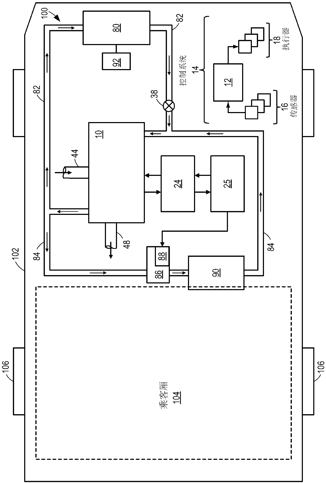
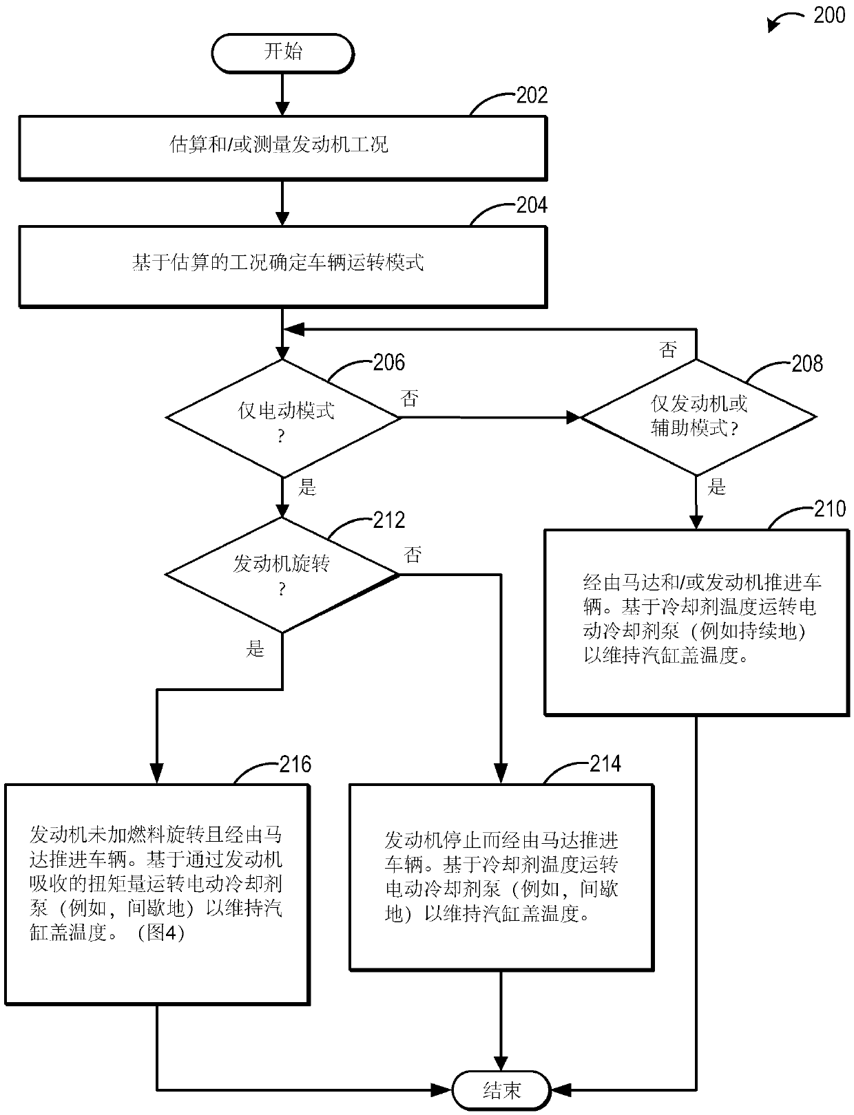
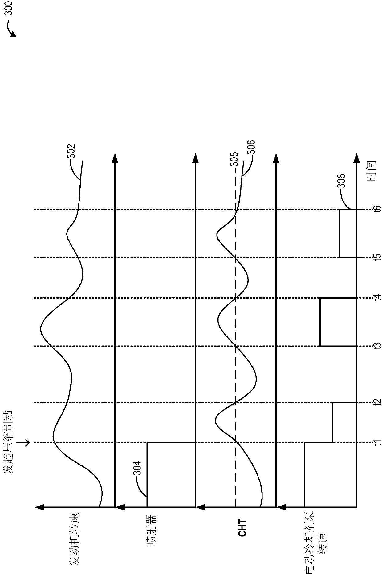
[0012] The instructions below relate to adjusting the auxiliary engine coolant pump based on the amount of engine compression braking torque (e.g. figure 1 A method and system for the operation of a coolant pump). During conditions when the vehicle is propelled by the motor and the engine is spinning without fuel, heat generated by the engine due to torque absorption may be dissipated by operating the engine coolant pump. The controller can be configured to execute control programs such as figure 2 Example method of ) to operate the engine coolant pump based on vehicle speed and compression braking torque in order to maintain engine temperature below a threshold. reference here image 3 Operation of an example coolant pump is described. In this way, the temperature of the engine can be maintained even during compression braking without reducing the efficiency of the coolant pump.

[0013] now go to figure 1 , schematically illustrates an example embodiment of a cooling s...


PUM


Abstract

Methods and systems are provided for adjusting the operation of an electric coolant pump in a hybrid vehicle system. During vehicle compression braking conditions, a motor propels the vehicle while the engine spins un-fueled to absorb torque. During such conditions, the coolant pump is operated based on the absorbed torque to maintain an engine temperature within a threshold.

Description

【Technical field】 [0001] The present invention generally relates to a control system for maintaining engine temperature during extended periods of compression braking. 【Background technique】 [0002] Engines may be equipped with a mechanical coolant pump that circulates coolant through the cylinder heads in addition to providing heat to the vehicle's passenger compartment. The engine control system may be configured to regulate operation of the coolant pump based on engine temperature in order to maintain cylinder head temperature. In some vehicle systems, such as hybrid electric vehicles, an electric auxiliary pump may also be included to assist the main mechanical coolant pump. [0003] An example of an engine system is disclosed in US Patent Publication US2004 / 0103862 filed by Aidnik in which an auxiliary pump is used in conjunction with an engine driven pump. Of these, the mechanical coolant pump provides coolant circulation during most driving situations, while the el...

Claims


Application Information

Patent Timeline
IPC IPC(8): F01P7/16F01P7/04
CPCB60W30/18136B60W10/198B60W10/10B60W10/06B60W2510/244B60Y2300/46B60W2710/0688F01P2050/24B60W20/00F01P7/164B60H1/04F01P7/162F01P7/14Y10S903/93B60W30/143
Inventor O·A·阿比哈那
Owner FORD GLOBAL TECH LLC
Features
  • R&D
  • Intellectual Property
  • Life Sciences
  • Materials
  • Tech Scout
  • Unparalleled Data Quality
  • Higher Quality Content
  • 60% Fewer Hallucinations
Learn More