Planet car wheel testing device
A test device and planetary car technology, which is applied in wheel testing and other directions, can solve problems such as large inertia and difficult testing experiments, and achieve the effect of reducing inertia
- Summary
- Abstract
- Description
- Claims
- Application Information
AI Technical Summary
Problems solved by technology
Method used
Image

Examples
specific Embodiment approach 1
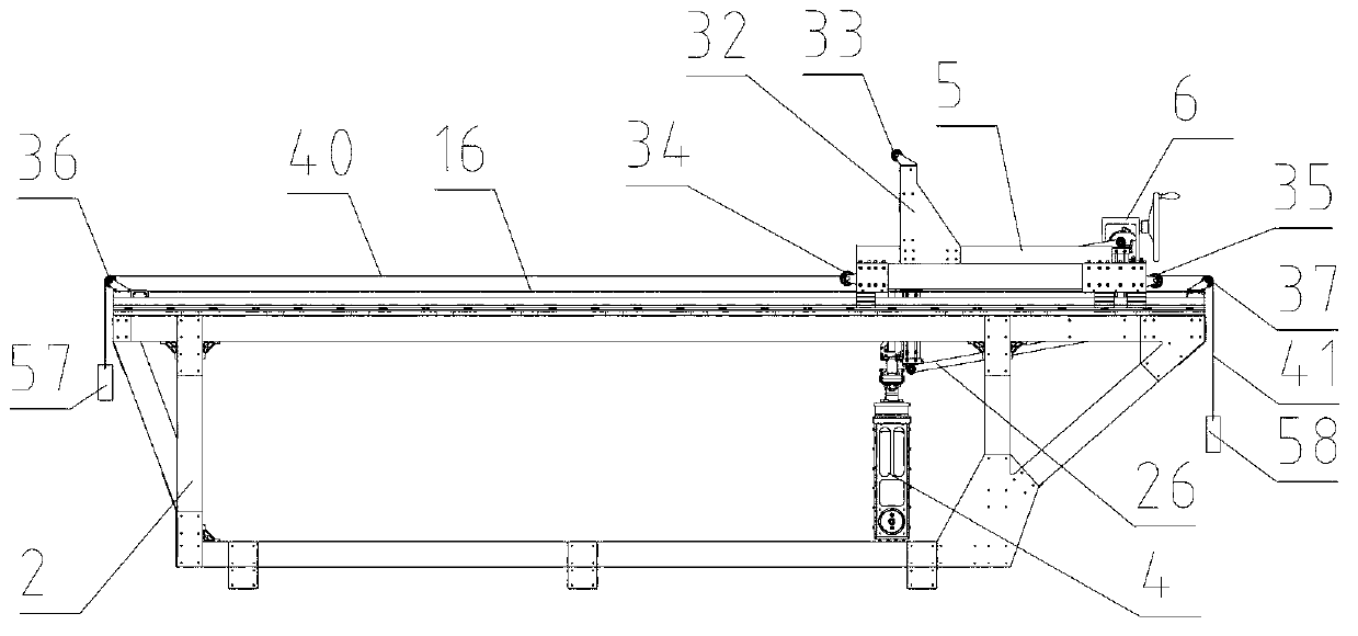
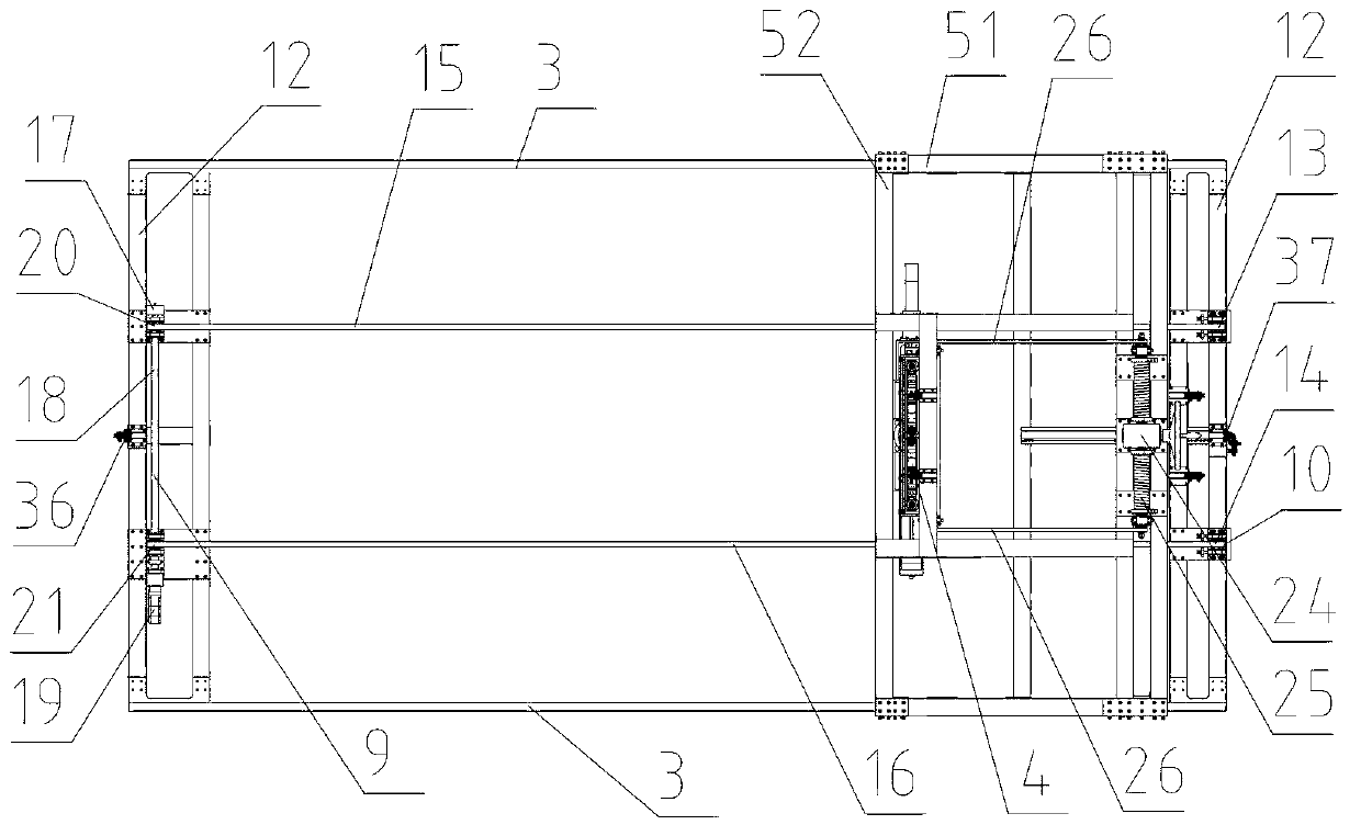
[0007] Specific implementation mode one: combine figure 1 , figure 2 , image 3 , Figure 4 , Figure 5 , Figure 6 , Figure 10 and Figure 11 Describe this embodiment mode, a planetary vehicle wheel testing device described in this embodiment mode, the device includes a bracket 2, a wheel frame 4, a loading mechanism 6, a trolley 5, a speed measuring and active mechanism 9 and a passive pulley mechanism 10, the Two horizontal underframes 12 are arranged on the left and right sides of the upper end of the support 2, and the two horizontal underframes 12 are respectively fixedly connected with the two ends of the two slide rails 3, and the two slide rails 3 are parallel to each other. The lower end is provided with a chute 53, the trolley 5 is arranged on the bracket 2 and the two slide rails 3 are respectively arranged in the chute 53, and the bases of the speed measuring and active mechanism 9 and the passive pulley mechanism 10 are respectively fixed on the left and ...
specific Embodiment approach 2
[0008] Specific implementation mode two: combination figure 1 , figure 2 , Figure 10 and Figure 11 Describe this embodiment, the joint of active motor 19 and coupling shaft 18 described in this embodiment is provided with gear type clutch 22, also is provided with second pulley 34 and the 3rd pulley 35 on described trolley 5, described left and right two A fourth pulley 36 and a fifth pulley 37 are respectively arranged on the horizontal underframe 12. One end of the first pulley rope 40 and the second pulley rope 41 is fixed, and the other end of the first pulley rope 40 goes around the second pulley 34 and the second pulley successively. Four pulleys 36, the other end of the second pulley rope 41 goes around the third pulley 35 and the fifth pulley 37 successively, and the free ends of the first pulley rope 40 and the second pulley rope 41 are respectively provided with the first loading block 57 and For the second loading block 58, other components and connections are...
specific Embodiment approach 3
[0009] Specific implementation mode three: combination figure 1 , Figure 8 , Figure 9 and Figure 10 Describe this embodiment, the wheel frame 4 described in this embodiment includes a driving motor 42, a counterweight balancing device 43, a wheel positioning frame 44, a six-dimensional force / moment sensor 45, a steering motor 48, a screw lifting mechanism 46 and a connecting plate 47. The wheel positioning frame 44 is an inverted "U"-shaped frame, and both ends of the wheel positioning frame 44 are provided with a wheel positioning shaft, and the wheel positioning shaft at one end of the wheel frame 4 is rotationally connected to the output end of the drive motor 42 , the counterweight balance device 43 is fixed on the wheel alignment shaft on the other side and the weight of the counterweight balance device 43 is the same as that of the drive motor 42, and the upper end of the wheel alignment frame 44 is fixedly provided with a six-dimensional force / torque sensor 45, six...
PUM
 Abstract
Description
Claims
Application Information
 - Generate Ideas
- Intellectual Property
- Life Sciences
- Materials
- Tech Scout
- Unparalleled Data Quality
- Higher Quality Content
- 60% Fewer Hallucinations
Browse by: Latest US Patents, China's latest patents, Technical Efficacy Thesaurus, Application Domain, Technology Topic, Popular Technical Reports.
© 2025 PatSnap. All rights reserved.Legal|Privacy policy|Modern Slavery Act Transparency Statement|Sitemap|About US| Contact US: help@patsnap.com