Molded package and light emitting device

A technology of light-emitting devices and molded bodies, applied in the direction of electric solid devices, semiconductor devices, electrical components, etc., can solve the problems of aesthetic damage, etc., and achieve the effect of inhibiting intrusion, inhibiting leakage, and inhibiting the occurrence of burrs

Active Publication Date: 2013-07-24
NICHIA CORP
View PDF2 Cites 1 Cited by
  • Summary
  • Abstract
  • Description
  • Claims
  • Application Information

AI Technical Summary

Problems solved by technology

In addition, since the burr 80 has an irregular shape, the appearance of the concave portion 120 of the molded package 100 is impaired in a plan view ( Figure 17 )

Method used


Image

  • Molded package and light emitting device
  • Molded package and light emitting device
  • Molded package and light emitting device

Examples


Embodiment approach 1

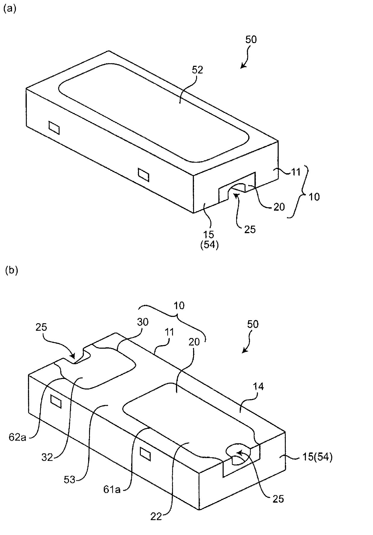
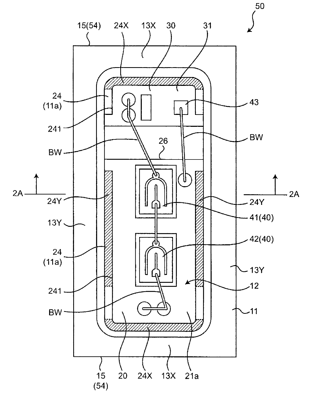
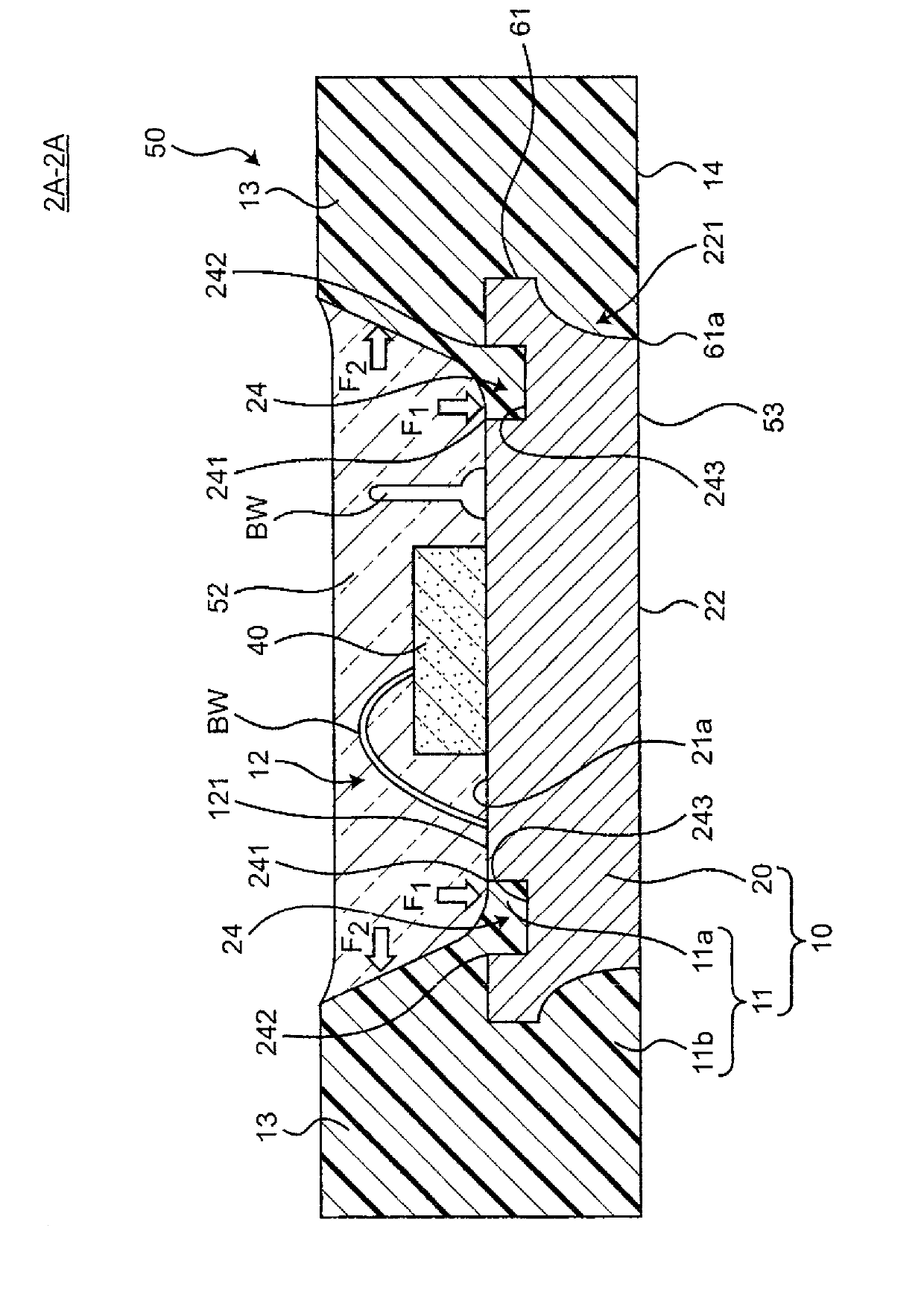
[0062] Such as Figure 1~3 As shown, a light-emitting device 50 of the present invention includes a molded package 10 , a light-emitting component 40 and an encapsulating resin 52 .

[0063] The so-called "light-emitting component 40" in this specification refers to a component including a light-emitting element, including a light-emitting element (such as an LED) itself, or a component composed of a light-emitting element and a submount (submount: submount). In this embodiment, the light emitting component 40 is constituted by a light emitting element.

[0064] As for the encapsulating resin 52 , it encapsulates the concave portion 12 of the resin molded body 11 containing the light emitting component 40 and protects the light emitting component 40 from the external environment.

[0065] The molded package 10 of the present invention includes a molded resin 11 and at least one lead (in this embodiment, two leads 20 and 30 ).

[0066] The resin molded body 11 has a recessed ...

Embodiment 1

[0142] As an example of the present invention, the molded package 10 and the molded package 100 for comparison were produced, and the presence or absence of the burr 80 was confirmed.

[0143] The manufacturing process of the molded package 10 of the present invention is as follows. First, wet etching is performed on the lead frame LF in which the first lead 20 and the second lead 30 are connected by the tie bar TB, and after forming the groove portion 24 at a predetermined position, the lead frame LF is clamped by the mold 90, and the resin is injected into the mold 90. Then, an assembly of the molded package 10 is formed. Next, the molded resin body 11 and the tie bar TB are cut by dicing along predetermined positions to separate the molded package 10 into individual pieces.

[0144] The molded package 100 for comparison is the same as the manufacturing process of the molded package 10 of the present invention except that the process of forming the groove portion 24 at a pr...


PUM


Abstract

A molded package includes a molded resin and a lead. The molded resin has a recess portion provided on an upper surface of the molded resin to accommodate a light emitting component. The lead is partially exposed from a bottom surface of the recess portion of the molded resin to be electrically connected to the light emitting component and extends below a side wall of the recess portion. The lead has a groove formed on a surface of the lead at least partially along the side wall. The groove has an inside upper edge and an outside upper edge and is filled with the molded resin so that the inside upper edge is exposed from the bottom surface of the recess portion and the outside upper edge is embedded within the molded resin.

Description

technical field [0001] The present invention relates to a molded package for a light-emitting device and a light-emitting device using the same. Background technique [0002] In the frame insertion type resin package for light-emitting devices, it is known that by exposing the leads on the back surface of the resin molded body, the heat radiation from the light-emitting components placed in the concave portion of the package can be efficiently released to the mounting substrate through the leads. (eg, Patent Document 1). Also known is a package in which an anchoring groove is formed on a lead and a resin molded body is filled in the anchoring groove to increase the contact area between the lead wire and the resin molded body (for example, Patent Document 2). [0003] 【Prior technical literature】 [0004] 【Patent Literature】 [0005] [Patent Document 1] JP-A-2008-251937 [0006] [Patent Document 2] Japanese Patent Laid-Open No. 2011-146524 [0007] In the light-emitting ...

Claims


Application Information

Patent Timeline
Patent Type & Authority Applications(China)
IPC IPC(8): H01L33/48H01L33/54H01L33/62
CPCH05K1/0313H01L33/486H01L2224/48091H01L33/62H01L33/38H01L2224/48247H01L33/54H01L33/56H01L2924/00014H01L2924/18301
Inventor 笹冈慎平中林拓也
Owner NICHIA CORP
Why Eureka
Try Eureka