
Direct-current transmission converter valve control protection system and control protection method thereof

A technology of control protection and direct current transmission, applied in the direction of direct current network circuit devices, electrical components, circuit devices, etc., can solve the problems of stable operation of the system, complex coding, passive monitoring, etc., to reduce downtime and maintenance time, intelligent The effect of high level of chemicalization and improved stability

Active Publication Date: 2013-07-24
GLOBAL ENERGY INTERCONNECTION RES INST CO LTD +2
View PDF3 Cites 47 Cited by
  • Summary
  • Abstract
  • Description
  • Claims
  • Application Information

AI Technical Summary

Problems solved by technology

[0002] The redundant design of the traditional converter valve control and protection system is not perfect, only one system can receive the return information from the converter valve, and the switching time of the master-slave system is long, which has a great impact on the DC transmission system
In order to reduce the number of triggering optical fibers, some converter valve control and protection systems use optical splitter design on the high-voltage side, but the reliability of the optical splitter is poor, which increases the instability of the system
Moreover, the traditional DC converter valve triggering and monitoring unit has problems such as passive monitoring, complex coding, and lack of fast energy acquisition, all of which affect the stable operation of the system

Method used


Image

  • Direct-current transmission converter valve control protection system and control protection method thereof
  • Direct-current transmission converter valve control protection system and control protection method thereof
  • Direct-current transmission converter valve control protection system and control protection method thereof

Examples


Embodiment Construction

[0038] The specific implementation manners of the present invention will be further described in detail below in conjunction with the accompanying drawings.

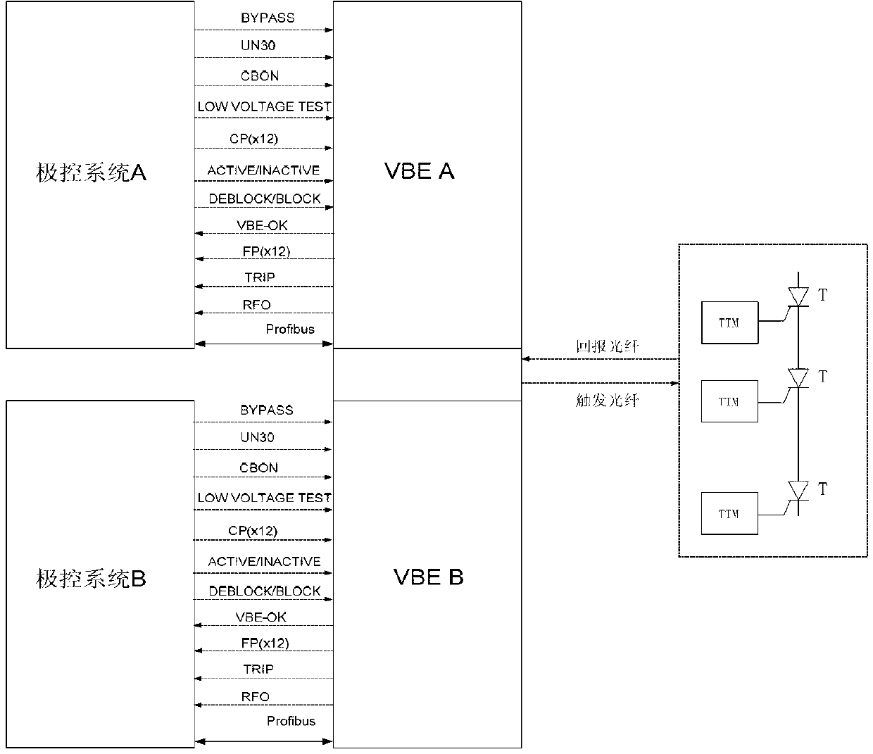
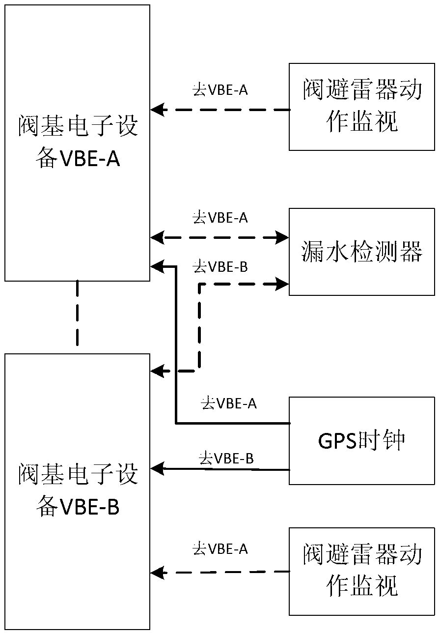
[0039] The principle diagram of the converter valve control and protection system provided by the present invention is as follows: figure 1 As shown, the converter valve control and protection system is mainly composed of thyristor trigger monitoring unit (TTM), valve-based electronic equipment (VBE), extreme control system and connecting optical fiber, among which the extreme control system and valve-based electronic equipment VBE are completely Independent dual redundant systems are defined as extreme control system A and extreme control system B; VBE-A and VBE-B. principle such as figure 1 As shown, the extreme control system A and VBE-A form an independent system, and the extreme control system B and VBE-B form an independent system. During normal operation, one set is the main system (operating system) and the othe...


PUM


Abstract

The invention relates to the field of direct-current transmission, in particular to a direct-current transmission converter valve control protection system and a control protection method thereof. The control protection system is formed by an operation system and a hot spare system which are in redundancy. The operation system and the hot spare system comprise a pole control system and valve base electronic equipment communicated with the pole control system respectively, the operation system and the hot spare system are connected with a thyristor triggering monitoring subsystem through optical fibers, and the thyristor triggering monitoring subsystem comprises a thyristor and a thyrustor triggering monitoring unit matched with the thyristor. Protection objects of the protection method comprise a converter valve and the valve base electronic equipment. The action results of the protection method comprise alarm, request switch and request trip. The direct-current transmission converter valve control protection system greatly improves operation stability of the direct-current transmission system, greatly reduces shutdown time and overhaul time of the direct-current transmission system and enables economical benefit advantages of the direct-current transmission system to be fully played.

Description

technical field [0001] The invention relates to the field of direct current transmission, in particular to a control and protection system for a direct current transmission converter valve and a control and protection method thereof. Background technique [0002] The redundant design of the traditional converter valve control and protection system is not perfect. Only one system can receive the feedback information from the converter valve, and the switching time of the master-slave system is long, which has a great impact on the DC transmission system. Some converter valve control and protection systems use optical splitters on the high-voltage side to reduce the number of trigger fibers, but the reliability of the optical splitters is poor, which increases the instability of the system. Moreover, the traditional DC converter valve triggering and monitoring unit has problems such as passive monitoring, complex coding, and no fast energy acquisition, all of which affect the ...

Claims


Application Information

Patent Timeline
IPC IPC(8): H02J13/00H02J1/00
Inventor 汤广福郝长城陈龙龙查鲲鹏周亮解海宁
Owner GLOBAL ENERGY INTERCONNECTION RES INST CO LTD
Learn More