
Stator chute machining tool and stator chute machining method

A stator and chute technology, applied in the mechanical field, to achieve the effect of weakening the cogging effect, fast positioning, and simple structure

Active Publication Date: 2013-07-24
ZHEJIANG LINIX MOTOR
View PDF7 Cites 6 Cited by
  • Summary
  • Abstract
  • Description
  • Claims
  • Application Information

AI Technical Summary

Problems solved by technology

But now there is no very convenient tool for machining stator chute, so it is very necessary to design a tool for processing stator chute that is convenient, fast and efficient

Method used


Image

  • Stator chute machining tool and stator chute machining method
  • Stator chute machining tool and stator chute machining method
  • Stator chute machining tool and stator chute machining method

Examples


Embodiment Construction

[0026] Below in conjunction with accompanying drawing, the present invention will be further described:

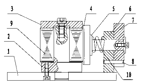
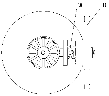
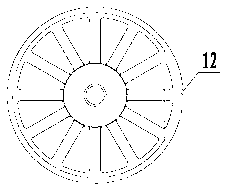
[0027] The stator chute processing tooling includes the stator core fixing device and the stator chute forming device. The stator core fixing device is composed of a bottom plate 1, a positioning mandrel 2 and a pressure plate 3. The positioning mandrel 2 is screwed on the bottom plate 3 for positioning. The top of the mandrel 2 is screwed with a pressure plate 3. During processing, the stator core sheet 9 is sleeved and arranged on the positioning core shaft, and then the pressure plate is fixed on the positioning core shaft with bolts to realize the positioning of the stator core core 9; The chute forming device is composed of a fixed plate 6, an angle plate 7 and a parallel positioning mandrel 5. The fixed plate 6 is fixedly arranged on the bottom plate 1, and the center of the fixed plate 6 is rotated to set a parallel positioning mandrel 5. The parallel positioning man...


PUM


Abstract

The invention belongs to the field of machinery and particularly relates to a stator chute machining tool and a stator chute machining method. The stator chute machining tool comprises a stator iron core piece fixing device and a stator chute forming device. The stator iron core piece fixing device is composed of a base plate, a positioning mandrel and a pressing plate, wherein the positioning mandrel is arranged on the base plate in a screw joint mode, the pressing plate is arranged at the top end of the positioning mandrel in a screw joint mode, and stator iron core pieces are sleeved on the positioning mandrel. The stator chute forming device is composed of a fixing plate, an angle plate and a parallel positioning mandrel, wherein the fixing plate is fixedly arranged on the base plate, the parallel positioning mandrel is arranged in the center of the fixing plate in a rotating mode, a positioning rib which is matched with stator iron core piece grooves is arranged at one end, close to the stator iron core pieces, of the parallel positioning mandrel, and the other end of the parallel positioning mandrel penetrates through the fixing plate to be sleeved with and fix the angle plate. The stator chute machining tool rapidly and efficiently machines stator chutes, inclined angles of the chutes are controlled when a positioning pin is matched with a positioning pin stroke hole, and a stator chute iron core can effectively weaken the effect of teeth and slots of a motor.

Description

technical field [0001] The invention belongs to the field of machinery, and in particular relates to a tool for processing stator inclined slots and a method for processing stator inclined slots. Background technique [0002] Permanent magnet synchronous motors are small in size, light in weight, high in efficiency, and high in power factor. They have gradually replaced asynchronous motors in many fields, but permanent magnet motors also have some disadvantages. The cost of synchronous motors is greatly increased; the pulse vibration generated by the inherent tooth increase torque of permanent magnet motors, and the permanent magnets may lose their magnetism under the condition of motor short circuit, etc. Therefore, a reasonable electromagnetic structure should be adopted in the design of the motor, which can not only effectively control the cost of the motor, but also improve the life of the motor. [0003] Due to the interaction between the stator core slot of the perman...

Claims


Application Information

Patent Timeline
IPC IPC(8): H02K15/02B23K26/20B23K26/42B23K26/21B23K26/70
Inventor 朱炎钊黄亮
Owner ZHEJIANG LINIX MOTOR
Learn More