
Distributed loop overlap space time code transmission method based on bidirectional multi-relay network

A transmission method and relay network technology, applied in the field of distributed space-time code transmission and two-way relay network, can solve the problems of high detection complexity at the receiving end and not considering the joint processing of signals received by multiple antennas.

Active Publication Date: 2013-07-24
XIDIAN UNIV
View PDF4 Cites 5 Cited by
  • Summary
  • Abstract
  • Description
  • Claims
  • Application Information

AI Technical Summary

Problems solved by technology

The solution is to use multiple relay nodes configured with single antennas to linearly encode the signal received from the source node and then send it to the destination node, but this solution is only applicable to the relay network with the relay node configured with a single antenna. When there are multiple antennas, the characteristics that the signals received by multiple antennas can be jointly processed are not considered
In 2009, when J.Harshan and B.S.Rajan considered that the relay node had dual antennas, they proposed a A coordinate interleaving distributed space-time code design scheme, but this scheme requires that the number of transmitted signals in a code block is more than twice the number of relay antennas, and requires a computer to search to obtain full diversity, resulting in high detection complexity at the receiving end

Method used


Image

  • Distributed loop overlap space time code transmission method based on bidirectional multi-relay network
  • Distributed loop overlap space time code transmission method based on bidirectional multi-relay network
  • Distributed loop overlap space time code transmission method based on bidirectional multi-relay network

Examples


Embodiment Construction

[0032] The technical method of the present invention will be described in further detail below with reference to the accompanying drawings and embodiments.

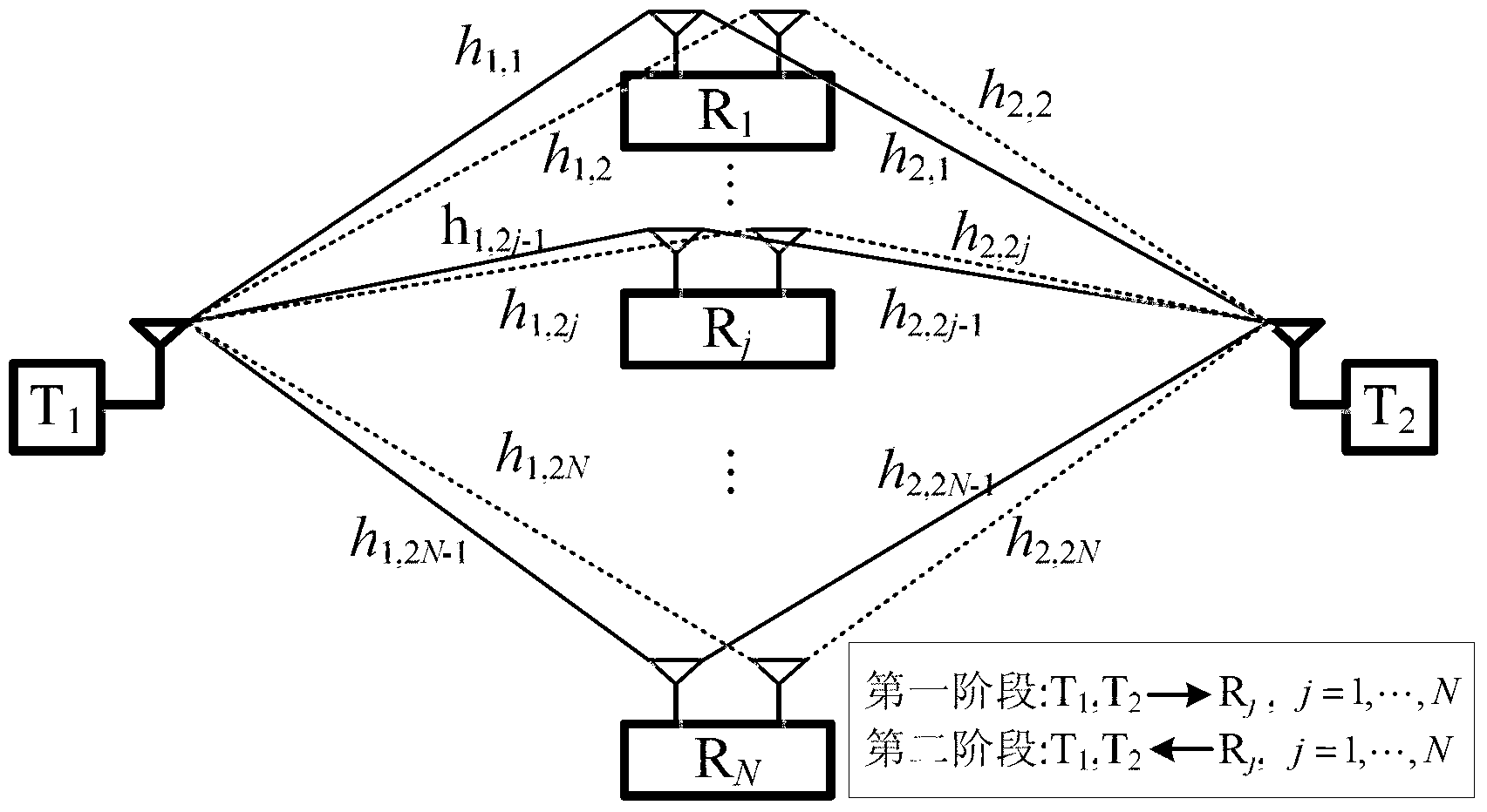
[0033] refer to figure 1 , the present invention is applicable to two source nodes T in the system 1 , T 2 Configure single antenna respectively, N relay nodes R j Configure dual antennas separately, where j=1,...,N, N=2 b , b is a non-negative integer, and it is assumed that the sum of the transmission powers of the two source nodes and all relay nodes is 1.

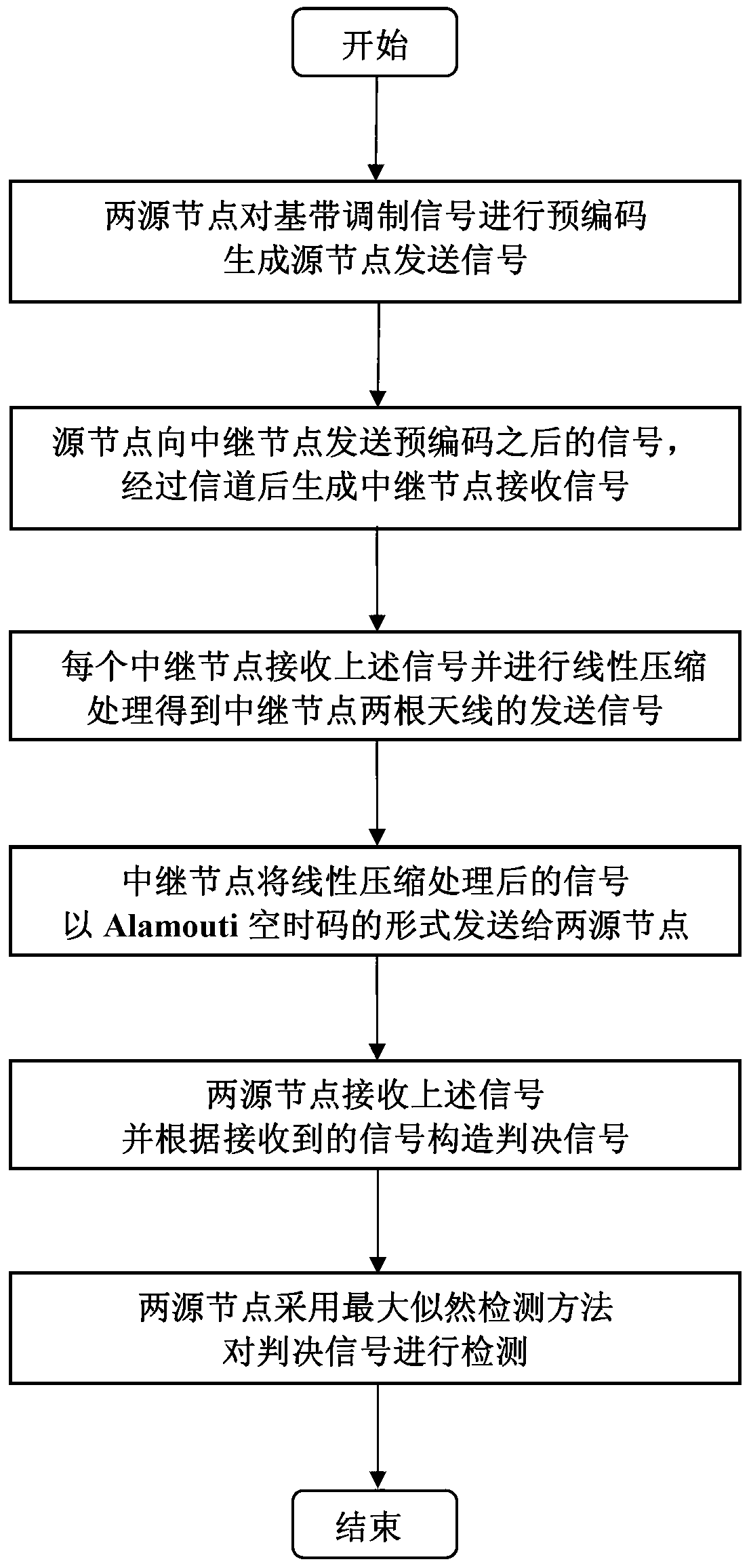
[0034] In Phase I, two source nodes T 1 , T 2 Respectively for the baseband modulated signal x 1 、x 2 After precoding, send it to N relay nodes, and the relay node R j Receive the signal sent by the source node and get the signal r received by the relay node j ;

[0035] In the second stage, the relay node R j For the received signal r j Perform linear compression processing and send to two source nodes T through its two antennas in a certain form 1 , T ...


PUM


Abstract

The invention discloses a distributed loop overlap space time code transmission method based on a bidirectional multi-relay network. The problems that the diversity gain is low, the error rate performance is poor and the detector is complex in the prior art are mainly solved. The method comprises the following implementation steps: two source nodes perform precoding on a baseband modulation signal to obtain a source node transmission signal; the two source nodes simultaneously transmit the precoded signal to all relay nodes; all the relay nodes receive the signals transmitted by the two source nodes; each relay node performs linear compression processing on the received signal, so that transmission signals on two antennas can be obtained and are transmitted to the two source nodes; and the two source nodes receive the signals transmitted by the relay nodes and construct a determination signal, and finally the determination signal is detected by employing a maximum likelihood detection method. The method has the advantages of improving the error rate performance of the system, obtaining the full diversity gain and maximum coding gain and lowering the complexity of the detector and can be used for bidirectional multi-relay network transmission.

Description

technical field [0001] The invention belongs to the field of wireless communication, and relates to a distributed space-time code transmission method, which can be used in a two-way relay network including two source nodes and multiple relay nodes, where the source node is configured with a single antenna and the relay node is configured with dual antennas . Background technique [0002] Relay transmission refers to a transmission method that uses relay nodes to assist source nodes and destination nodes to communicate. In the two-way relay network, two source nodes use the relay node to send information to each other at the same time, which is more spectrally efficient than the general one-way relay communication. In order to obtain diversity gain, the relay node can process the received signal and then send it to two source nodes in a certain form, and the source node can obtain the transmitted signal estimate according to the received signal detection. [0003] In 2006, ...

Claims


Application Information

Patent Timeline
IPC IPC(8): H04L1/06H04B7/15
Inventor 宫丰奎杨娜葛建华王勇张南李靖
Owner XIDIAN UNIV
Learn More