Signaling resource allocation method for uplink demodulation reference signals and base station
A technology for demodulating reference signals and signaling resources, which is applied in the field of signaling resource allocation for uplink demodulation reference signals, and can solve problems such as inability to support inter-cell user configuration and interference.
- Summary
- Abstract
- Description
- Claims
- Application Information
AI Technical Summary
Problems solved by technology
Method used
Image
Examples
Embodiment 1
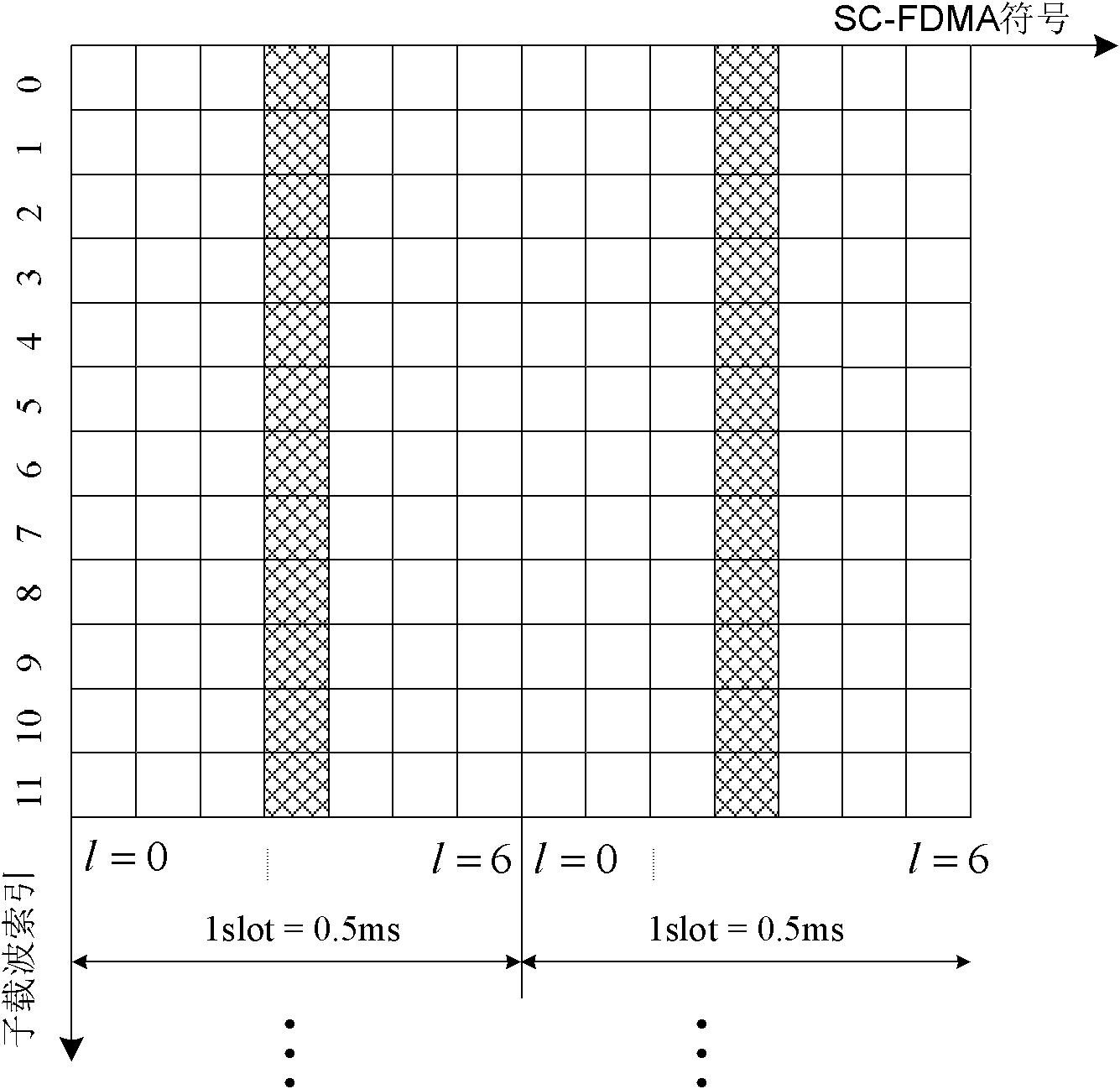
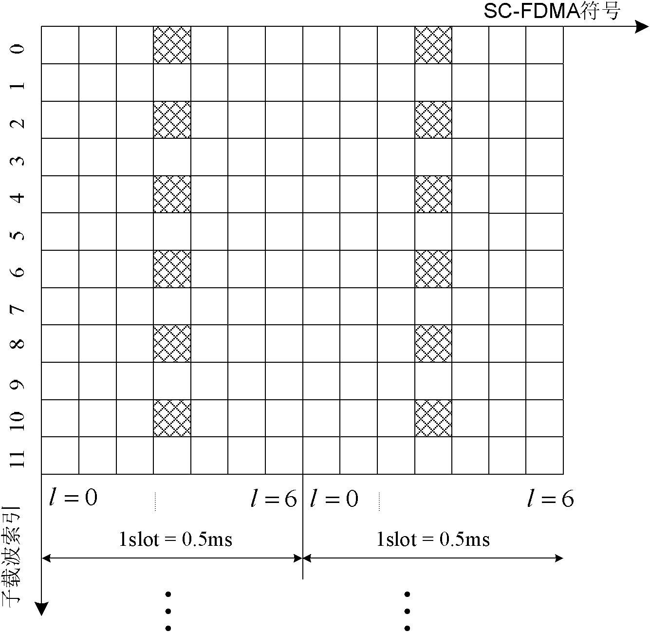
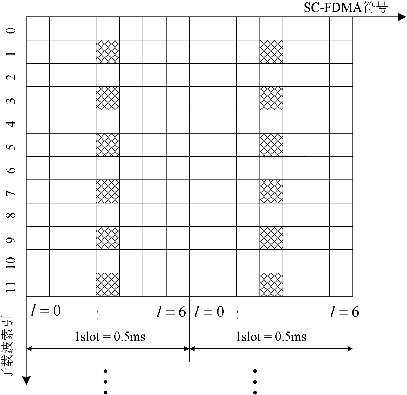
[0163] The network side jointly indicates the user's cyclic shift / orthogonal mask / subcarrier position through the original cyclic shift / orthogonal mask 3-bit signaling in the uplink control signaling of the downlink physical control channel. Preferably, the network side indicates the subcarrier position of the user on the uplink demodulation reference symbol of the allocated physical resource block as shown in Table 1:
[0164] Table 1 Joint indication of cyclic shift / orthogonal mask / subcarrier position
[0165]
[0166] Among them, in Table 1 Indicates the second cyclic shift value used on each layer by the uplink demodulation reference signal obtained by the user through the uplink control signaling of the downlink physical control channel, [w (λ) (0)w (λ) (1)] represents the orthogonal mask used by the user uplink demodulation reference signal on each layer. The value of comb indicates the subcarrier position occupied by the user DMRS: comb=i means that the user will...
Embodiment 2
[0180] The network side jointly indicates the user's cyclic shift / orthogonal mask / subcarrier position through the original cyclic shift / orthogonal mask 3-bit signaling in the uplink control signaling of the downlink physical control channel. Preferably, the network side indicates the subcarrier position of the user on the uplink demodulation reference symbol of the allocated physical resource block as shown in Table 2:
[0181] Table 2 Joint indication of cyclic shift / orthogonal mask / subcarrier position
[0182]
[0183] Among them, in Table 2 Indicates the second cyclic shift value of the uplink demodulation reference signal obtained by the user through the uplink control signaling of the downlink physical control channel, [w (λ) (0)w (λ) (1)] represents the orthogonal mask of the user uplink demodulation reference signal. The value of comb indicates the subcarrier position occupied by the user DMRS: comb=i means that the user will send the uplink demodulation referenc...
Embodiment 3
[0197] The network side jointly indicates the user's cyclic shift value and subcarrier position through the original 3-bit cyclic shift signaling in the radio resource control signaling (RRC). Preferably, the network side indicates the subcarrier position of the user on the uplink demodulation reference symbol of the allocated physical resource block as shown in Table 3:
[0198] Table 3 Joint indication of cyclic shift / subcarrier position
[0199]
[0200] Among them, in Table 3 Indicates the first cyclic shift value obtained by the user through radio resource control signaling. The value of comb indicates the subcarrier position occupied by the user in the uplink demodulation reference symbol of the allocated physical resource block: comb=i indicates that the user will use the even (odd) subcarrier index of the uplink demodulation reference symbol of the allocated physical resource block Send the uplink demodulation reference signal at the position; comb=j means that t...
PUM
 Abstract
Description
Claims
Application Information
 - R&D
- Intellectual Property
- Life Sciences
- Materials
- Tech Scout
- Unparalleled Data Quality
- Higher Quality Content
- 60% Fewer Hallucinations
Browse by: Latest US Patents, China's latest patents, Technical Efficacy Thesaurus, Application Domain, Technology Topic, Popular Technical Reports.
© 2025 PatSnap. All rights reserved.Legal|Privacy policy|Modern Slavery Act Transparency Statement|Sitemap|About US| Contact US: help@patsnap.com


