Downlink physical control channel sending method and receiving method and corresponding devices

A physical control channel and sending device technology, applied in wireless communication, communication between multiple stations, electrical components, etc., can solve problems such as limited bandwidth, inability to fully receive control information, and no solution proposed, to reduce cost, improve spectrum efficiency, and promote the effect of evolution

Active Publication Date: 2013-07-24
ZTE CORP
View PDF3 Cites 28 Cited by
  • Summary
  • Abstract
  • Description
  • Claims
  • Application Information

AI Technical Summary

Problems solved by technology

The most important thing is that the three downlink physical control channels are interleaved with the whole system bandwidth, and the MTC UE cannot fully receive the relevant control information due to the limited bandwidth.
Seriously affect the reception of LTE system downlink data and the transmission of MTC UE uplink data
[0013] For low-cost bandwidth-limited MTC UEs successfully receiving LTE downlink transmission data and how terminals access related issues, no effective solutions have been proposed so far

Method used


Image

  • Downlink physical control channel sending method and receiving method and corresponding devices
  • Downlink physical control channel sending method and receiving method and corresponding devices
  • Downlink physical control channel sending method and receiving method and corresponding devices

Examples


Embodiment 1

[0042]This embodiment describes the sending method of the downlink physical control channel, such as Figure 4 shown, including the following steps:

[0043] Step 101, the base station (eNodeB) maps the downlink physical control channel of the UE to the center frequency domain position of the system bandwidth of the second time slot of the subframe when sending the downlink physical control channel of the user equipment (UE);

[0044] Preferably, the UE includes an MTC UE, specifically, a low-cost MTC UE with limited bandwidth.

[0045] Preferably, when sending the downlink physical control channel of the UE, the eNodeB first judges whether the system bandwidth is greater than the first predefined bandwidth, and if so, maps the downlink physical control channel of the UE to the system bandwidth of the second time slot of the subframe If not (less than or equal to), send the downlink physical control channel (PCFICH, PDCCH, PHICH) of the UE according to the prior art. The wid...

Embodiment 2

[0073] This embodiment describes the receiving method of the downlink physical control channel, such as Figure 6 shown, including the following steps:

[0074] Step 201, UE judges whether the system bandwidth is greater than the first predefined bandwidth, if yes, execute step 202, otherwise execute step 203;

[0075] Preferably, the UE includes an MTC UE.

[0076] Step 202, the UE detects the downlink physical control channel at the central frequency domain position of the system bandwidth in the second time slot of the subframe; the width of the central frequency domain is the second predefined bandwidth, and the first predefined bandwidth is greater than or equal to the second predefined bandwidth. define the bandwidth;

[0077] The first predefined bandwidth is the maximum receiving bandwidth of the UE, and the second predefined bandwidth is the downlink control area bandwidth of the UE (or the system receiving bandwidth of the UE). Preferably, the first predefined ban...

application example 1

[0097] This example describes the case where the downlink physical control channel includes M-PCFICH, M-PHICH and M-PDCCH. In this example, the system bandwidth is 10MHz, while the transmit-receive bandwidth of the MTC UE is 1.4MHz, with 6 RBs.

[0098] The process of sending the channel on the eNodeB side is as follows: Figure 4 As shown, first, the eNodeB makes a judgment and compares the system bandwidth with the bandwidth predefined by the MTC UE. In this example, the system bandwidth is obviously greater than the bandwidth predefined by the MTC UE, so the Figure 8 The shown channel time-frequency mapping position sends the downlink physical control channel of the low-cost bandwidth-limited MTC UE:

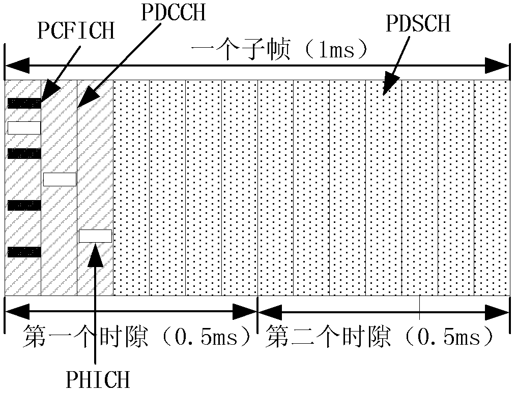
[0099] The frequency domain position of the entire control region is located in the center 6 RBs of the system bandwidth, and the time domain is the first 3 OFDM symbols in the second slot of the subframe. in:

[0100] The value of M-PCFICH is 2, 3 or 4. For each antenna...


PUM


Abstract

The invention discloses a downlink physical control channel sending method and a receiving method and corresponding devices. According to the downlink physical control channel sending method, when an eNodeB sends a downlink physical control channel of user equipment (UE), the downlink physical control channel of the UE is mapped onto the central frequency domain position of the system bandwidth of the second time slot of a subframe, and downlink control information of the UE is carried by the downlink physical control channel and sent. The downlink physical control channel sending device comprises a mapping module and a sending module. According to the downlink physical control channel receiving method, when the UE judges that the system bandwidth is larger than a first pre-defined bandwidth, the downlink physical control channel is detected at the central frequency domain position of the system bandwidth of the second time slot of the subframe, and the downlink control information of the UE is analyzed and obtained from the downlink physical control channel. The downlink physical control channel receiving device comprises a judging module, a detecting module and an analyzing module. According to the downlink physical control channel sending method and the receiving method and the corresponding devices, the cost of terminal equipment based on long term evolution (LTE) is reduced greatly on the basis that the system performance of the LTE is not affected, and original spectrum effectiveness can be improved.

Description

technical field [0001] The invention relates to the field of wireless communication, in particular to a method for sending and receiving a downlink physical control channel and a corresponding device. Background technique [0002] Machine Type Communication User Equipment (MTC UE for short), also known as M2M (Machine To Machine) user communication equipment, is the main application form of the Internet of Things at the present stage. Low power consumption and low cost are important guarantees for its large-scale application. At present, M2M technology has been supported by internationally renowned manufacturers such as NEC, HP, CA, Intel, IBM, AT&T, and recognized by mobile operators in various countries. Currently, M2M devices deployed in the market are mainly based on the GSM (Global System of Mobile communication, global mobile communication) system. In recent years, due to the high spectrum efficiency of LTE (Long Term Evolution, Long Term Evolution), more and more mo...

Claims


Application Information

Patent Timeline
Patent Type & Authority Applications(China)
IPC IPC(8): H04W72/14
CPCH04B7/26H04W72/14H04W72/04
Inventor 李新彩戴博夏树强方惠英石靖
Owner ZTE CORP
Why Eureka
Try Eureka