
Lathe and screw rod support device thereof

A support device and screw technology, applied in feeding devices, metal processing machinery parts, metal processing equipment, etc., can solve the problems of reduced processing accuracy, screw failure, screw deformation, etc.

Inactive Publication Date: 2013-07-31
GUANGDONG HARVEST START TECH CO LTD
View PDF5 Cites 0 Cited by
  • Summary
  • Abstract
  • Description
  • Claims
  • Application Information

AI Technical Summary

Problems solved by technology

Due to design requirements, some screws are very long, and the screw is completely deformed by its own weight only by the two ends, which leads to a decrease in machining accuracy and even failure of the screw.

Method used


Image

  • Lathe and screw rod support device thereof
  • Lathe and screw rod support device thereof
  • Lathe and screw rod support device thereof

Examples


Embodiment Construction

[0020] In order to make the technical solution of the present invention more clearly expressed, the present invention will be further described below in conjunction with the accompanying drawings.

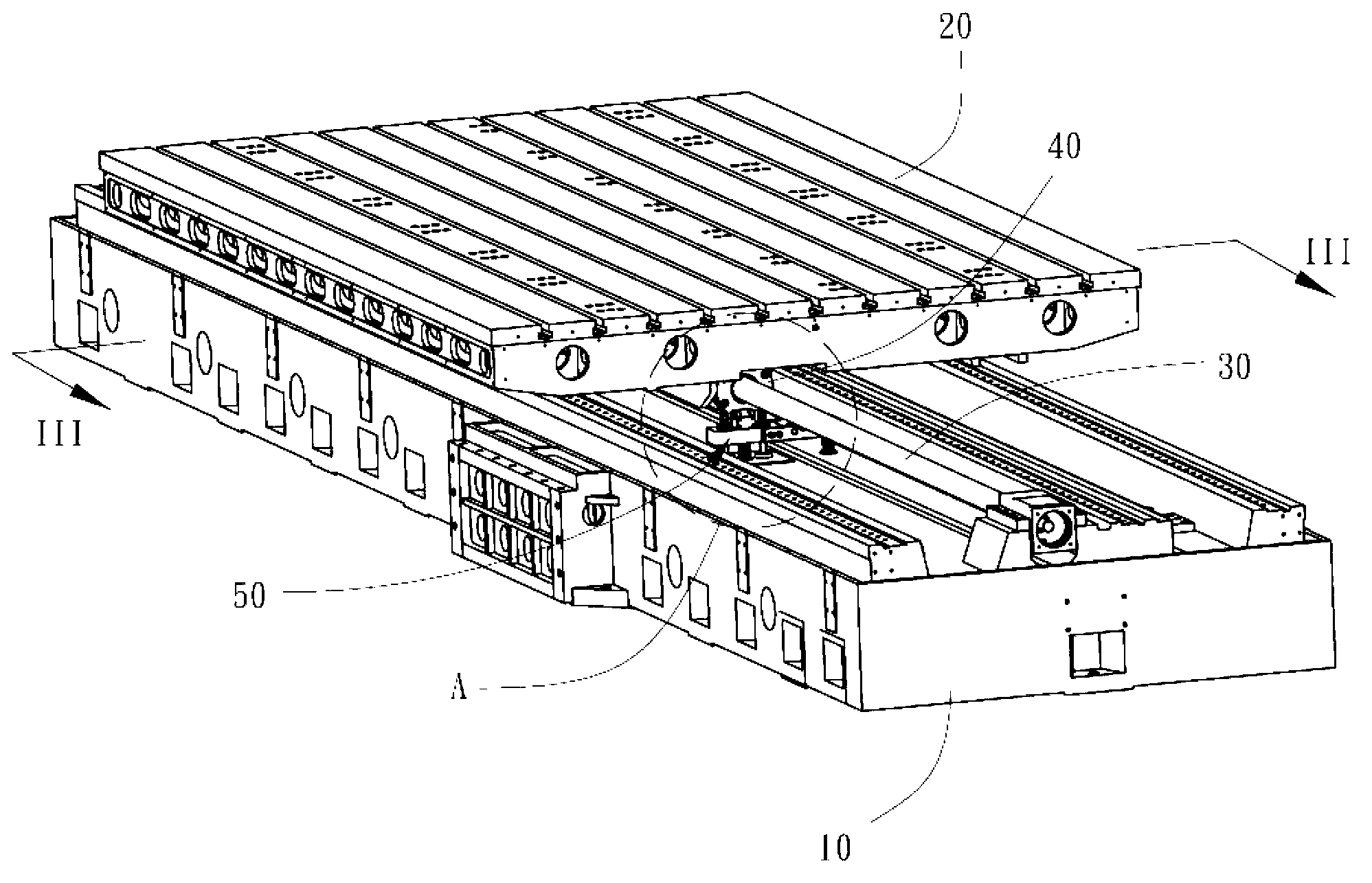
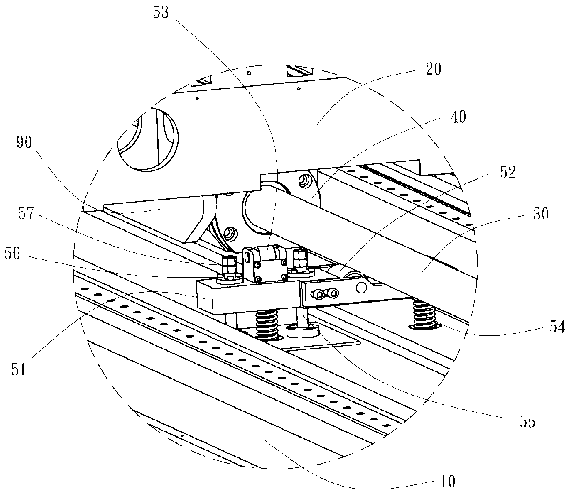
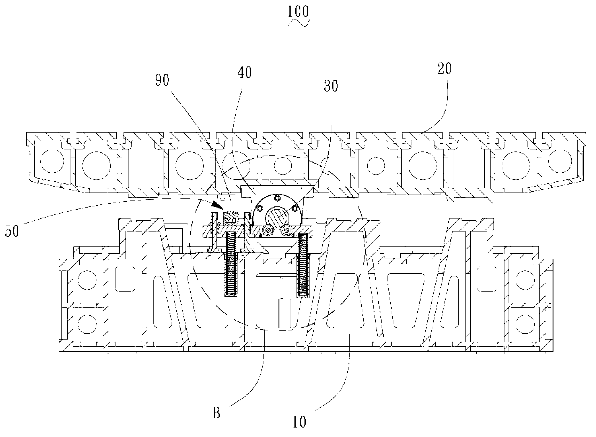
[0021] Such as figure 1 and figure 2 Shown is a machine tool 100 of a preferred embodiment of the present invention, and the machine tool 100 is a numerically controlled machine tool in this embodiment. The machine tool 100 includes a base 10 and a workbench 20 . The base 10 is equipped with a driving motor (not shown) and a screw 30 connected to the driving motor at one end, and the other end of the screw 30 is fixed on the base 10 through a bearing seat (not shown). A nut 40 mounted on the screw 30 is fixed at the bottom of the workbench 20 . When the screw 30 rotates, the nut 40 is driven to drive the workbench 20 to move back and forth along the axis of the screw 30 . The base 10 is further provided with a screw supporting device 50 , and the screw supporting device 50 elas...


PUM


Abstract

A lathe comprises a base, a motor mounted on the base, a screw rod connected with the motor, a nut connected with the screw rod and a workbench connected with the nut, and a screw rod support device arranged at the bottom of the screw rod as well, wherein the screw rod support device comprises a pedestal, supporting wheels and a pinch roller all mounted on the base, springs mounted between the pedestal and the base, a pressing block mounted at the bottom of the workbench and positioned on one side of the nut; the springs push the pedestal upwards to drive the supporting wheels to support the screw rod; when the nut rotates with the screw rod to move close to the screw rod support device, the pressing block squeezes the pinch roller to drive the pedestal and the supporting wheels to move downwards, so that the springs are pressed to shrink and deform, and the nut passes through the upper part of the pedestal and the supporting wheels; and when the pinch roller is not squeezed by the pressing block, the springs push the pedestal upwards to drive the supporting wheels to support the screw rod.

Description

technical field [0001] The invention relates to processing equipment, in particular to a machine tool and a screw support device thereof. Background technique [0002] In the existing mechanical processing equipment such as CNC machine tools and machining centers, most of the feed motion axes use motors as source power components and screws as power actuators. A general machine tool has a horizontal screw, such as an X-axis screw or a Y-axis screw. Due to design requirements, some screw rods are very long, and only relying on the two ends of the screw rod will often cause the screw rod to be completely deformed due to its own weight, resulting in a decrease in machining accuracy or even screw failure. This is not allowed for machine tools with high precision requirements. Contents of the invention [0003] Therefore, an object of the present invention is to provide a machine tool with a screw support device and the screw support device. [0004] A machine tool includes ...

Claims


Application Information

Patent Timeline
Patent Type & Authority Applications(China)
IPC IPC(8): B23Q5/40
Inventor 王仕平
Owner GUANGDONG HARVEST START TECH CO LTD
Learn More