A keeping unit and a line drawing device

A technology of scribing device and holder, which is applied to glass cutting devices, fine working devices, manufacturing tools, etc., can solve problems such as poor rotation of bearings and poor movement of holders, and achieve the effect of simple structure

Active Publication Date: 2013-07-31
MITSUBOSHI DIAMOND IND CO LTD
View PDF11 Cites 15 Cited by
  • Summary
  • Abstract
  • Description
  • Claims
  • Application Information

AI Technical Summary

Problems solved by technology

[0013] When such a conventional scribing device is used to scribing or breaking a brittle material substrate such as glass, there is a problem that foreign matter such as tiny glass shavings enters from the gap between the inner ring 52 and the sealing member 54, causing bearing damage. The rotation is poor, and the movement of the retainer is poor

Method used


Image

  • A keeping unit and a line drawing device
  • A keeping unit and a line drawing device
  • A keeping unit and a line drawing device

Examples


Embodiment approach 1

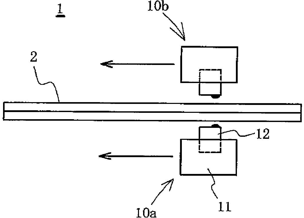
[0064] figure 1 A schematic diagram of the scribing device 1 according to the embodiment of the present invention is shown in . The scribing device 1 includes a support unit (not shown) that supports a brittle material substrate 2 such as a glass-bonded substrate such as a liquid crystal panel in advance. Furthermore, a scribing head 10 a is provided movably on the lower surface side of the brittle material substrate 2 , and a scribing head 10 b is movably provided on the upper surface side.

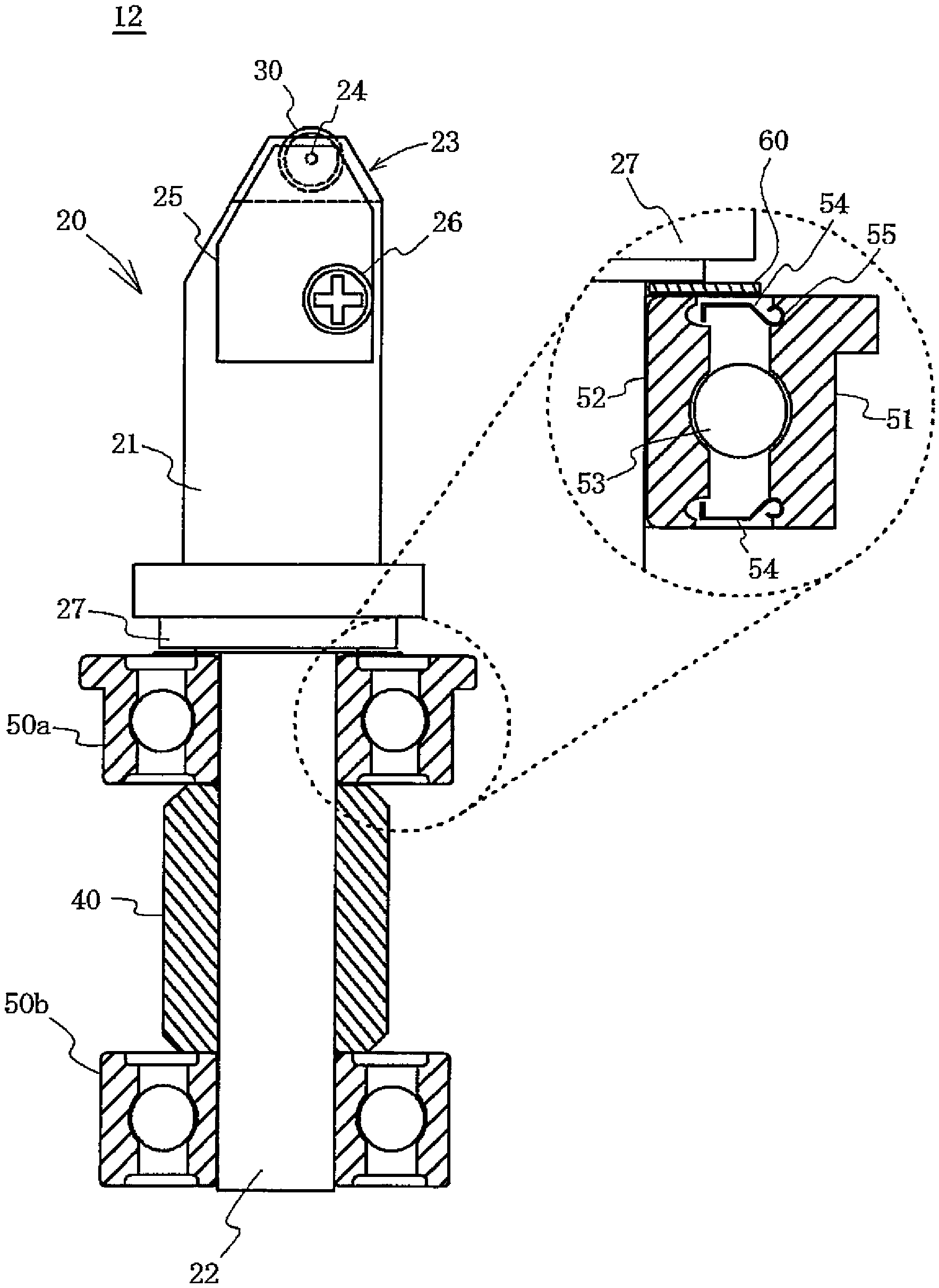
[0065] The scribing head 10 a includes a main body 11 and a holder unit 12 mounted on the main body 11 . In addition, details about the holder unit 12 will be described later. In addition, since the scribing head 10b has the same structure as the scribing head 10a, description is abbreviate|omitted.

[0066] In addition, although not particularly shown in the figure, the scribing device 1 includes an elevating mechanism for moving the scribing heads 10a, 10b closer to or away from th...

Embodiment approach 2

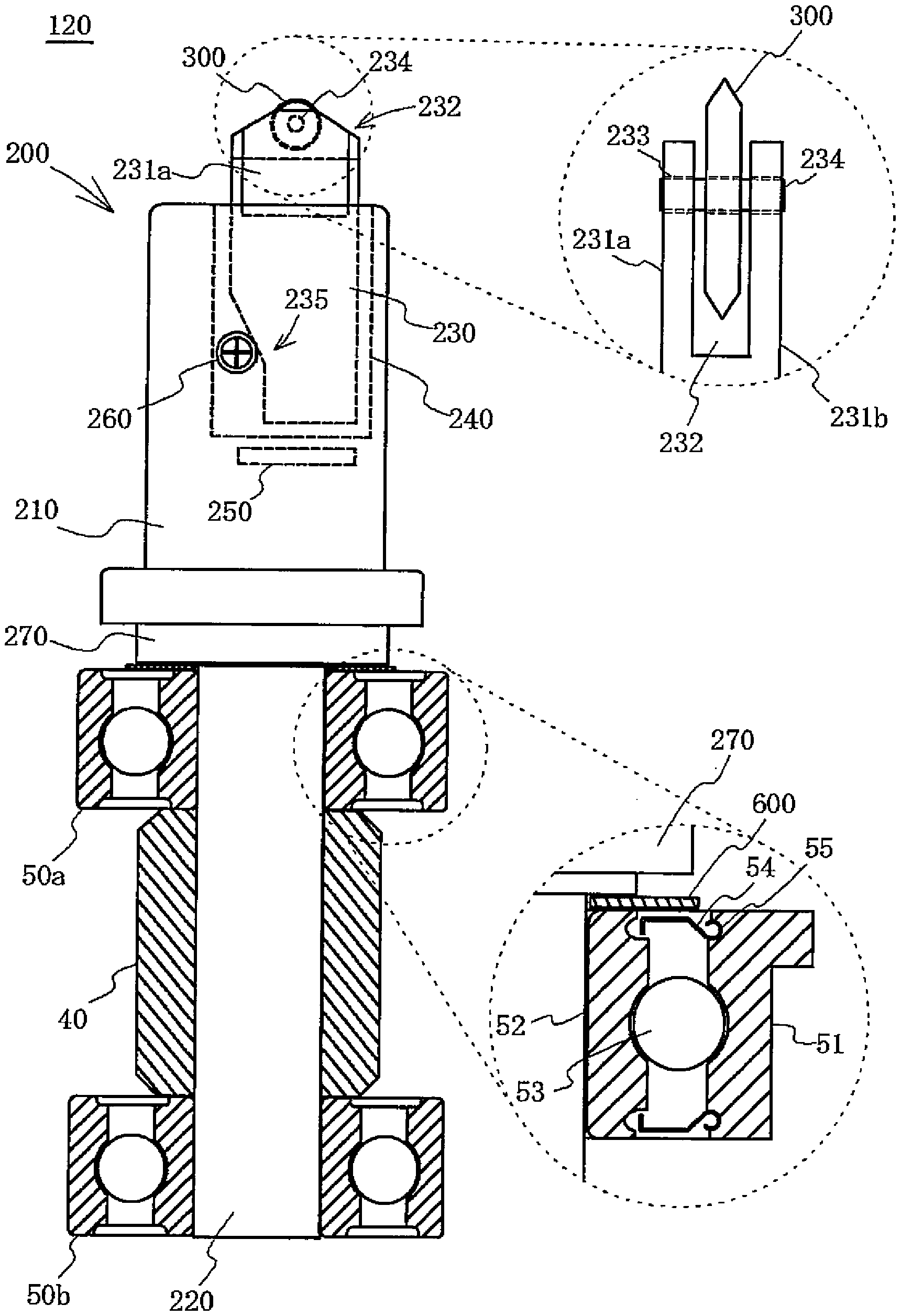
[0084] Like the scribing device 1 of Embodiment 1, the scribing device according to the embodiment of the present invention includes a scribing head on the lower surface side and the upper surface side of the brittle material substrate, respectively. Furthermore, holder units are respectively attached to the main body of the scribing head. image 3 The shown holder unit 120 is different in configuration from the holder unit 12 of the first embodiment. In addition, the same code|symbol is used about the same structure as the holder unit 12 of Embodiment 1, and description is abbreviate|omitted suitably.

[0085] The holder unit 120 includes a scribing wheel 300 , a holder 230 rotatably holding the scribing wheel 300 , and a cylindrical holder joint 200 including two bearings 50 a , 50 b and a cylindrical spacer 40 . in addition, image 3 A front view of the holder unit 120 is shown, and a cross-sectional view of the bearings 50a, 50b, and the spacer 40 is shown.

[0086] A h...

Embodiment approach 3

[0100] Next, Embodiment 3 will be described. Embodiment 3 is a holder unit 12a obtained by partially improving the holder unit 12 described in Embodiment 1. As shown in FIG. In addition, about the holder unit 12a, the same code|symbol is used for the same structure as the holder unit 12, and description is abbreviate|omitted. Figure 4 A front view of the holder unit 12a according to Embodiment 3 is shown in , and a cross-sectional view of the bearings 50a, 50b and the spacer 40 is shown.

[0101] The holder unit 12 a differs from the holder unit 12 in that a cylindrical cover 28 is attached to the outer periphery of the cylindrical portion of the wheel holding portion 21 . The cover 28 is a member formed of metal such as aluminum or resin, and has a size to cover the entire upper surface of the bearing 50a. By using this holder unit 12a, the gap between the main body 11 and the holder unit 12a can be made smaller than when the holder unit 12 without the cover 28 is used. T...


PUM

PropertyMeasurementUnit
thicknessaaaaaaaaaa

Abstract

The invention of the application relates to a keeping unit and a line drawing device. The line drawing device is equipped with line drawing heads on the top and the bottom of the line drawing device. And the line drawing head at the bottom is capable of preventing bad rotation caused by objects entering the bearing. In the line drawing head at the bottom of the line drawing device, on the top of a bearing (50a) of a keeping unit (12), a dustproof member (6) is configured in a manner in which a gap formed between an inner loop (52) and a sealing member (54) is stuffed. Therefore, objects such as glass chips generated when a hard brittle material substrate is fractured is not easy to enter the bearing (50a) from the gap.

Description

technical field [0001] The invention relates to a holder unit for forming scribe lines on brittle material substrates such as glass substrates, ceramic substrates, and silicon substrates, and a scribing device with the holder unit. Background technique [0002] Conventionally, in the manufacturing steps of flat display panels such as liquid crystal display panels and organic electroluminescence (EL, Electroluminescence) panels, solar cells, etc., there is a step of breaking brittle material substrates such as mother glass substrates. In this breaking step, a scribing device as described in Patent Document 1 is generally used. Furthermore, in the breaking step, while applying a load suitable for various conditions such as the material and thickness of the brittle material substrate to the scribing wheel included in the scribing device, the scribing wheel is placed on the surface of the brittle material substrate. A scribe line is formed by rolling, and a brittle material sub...

Claims


Application Information

Patent Timeline
Patent Type & Authority Applications(China)
IPC IPC(8): B28D5/00B28D1/24
CPCB26D3/08B28D5/00C03B33/033C03B33/10F16C33/763
Inventor 阪口良太佐々木吉也辻淳一
Owner MITSUBOSHI DIAMOND IND CO LTD
Why Eureka
Try Eureka