Electric fan with adjustable pitching angle
A pitch angle, electric fan technology, applied in the field of electric fans, can solve the problems of poor force bearing, troublesome operation, complex structure, etc., and achieve the effects of reliable positioning, convenient operation and large contact area
- Summary
- Abstract
- Description
- Claims
- Application Information
AI Technical Summary
Problems solved by technology
Method used
Image

Examples
Embodiment Construction
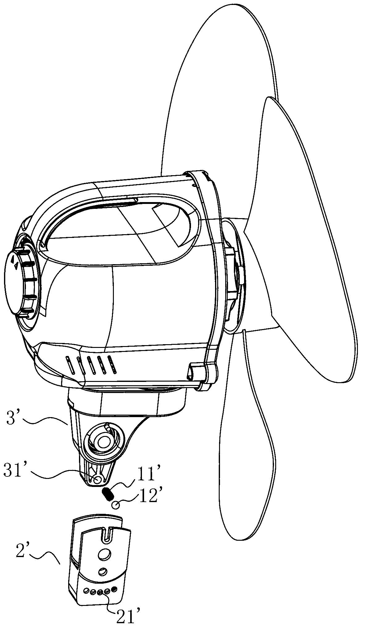
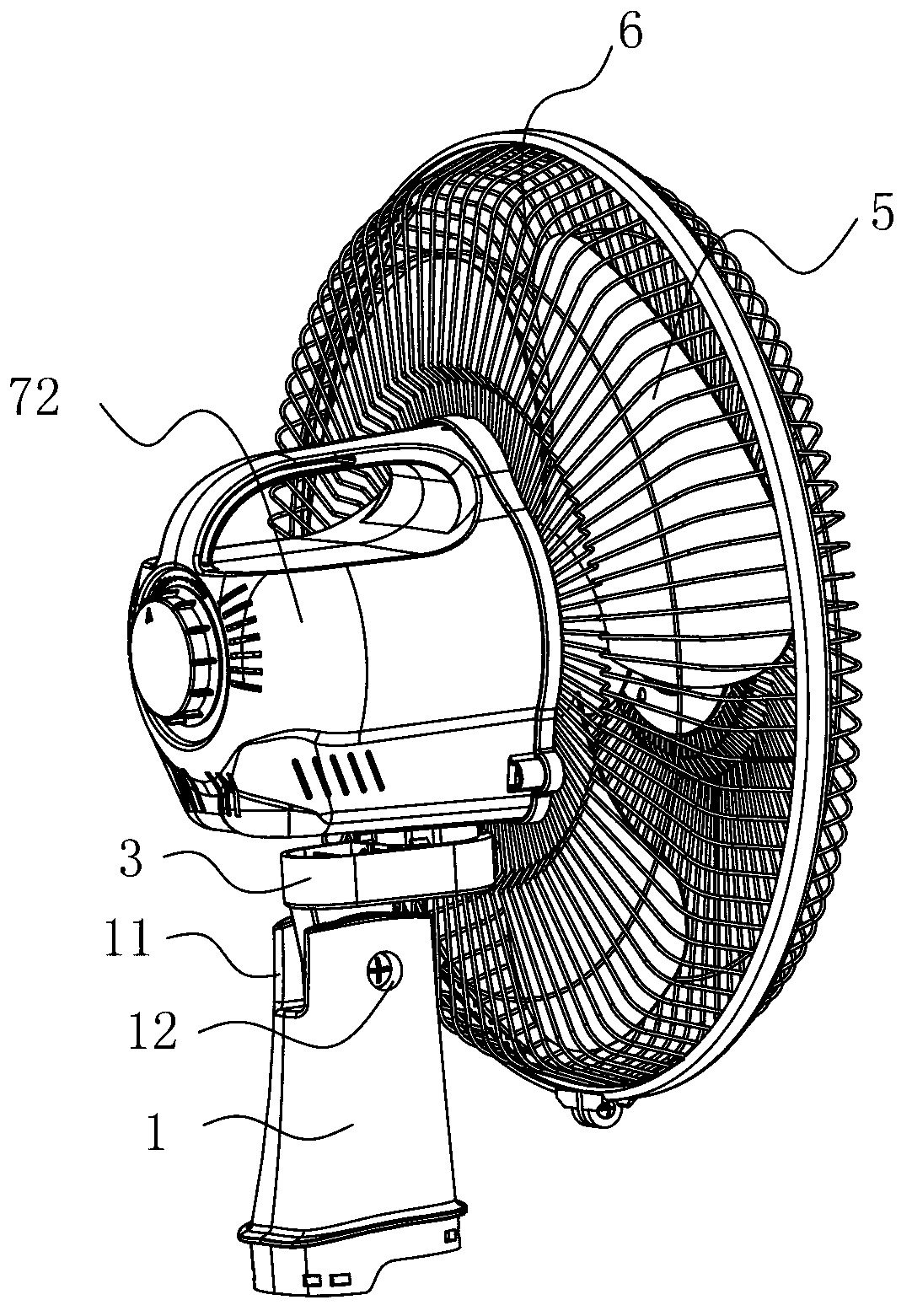
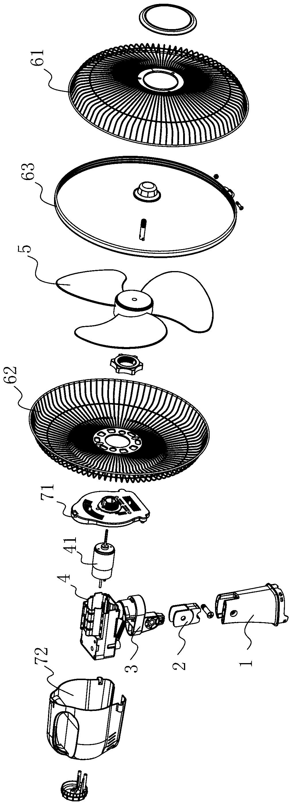
[0026] refer to Figure 2 to Figure 9 , an electric fan with adjustable pitch angle of the present invention, comprising a support frame 2 connected to the base, the upper end of the support frame 2 is hinged with a pitch turret 3 that can rotate up and down around the support frame 2, and the pitch turret 3 is arranged above There is an oscillating mechanism 4 that can rotate left and right relative to the pitching turret 3, and an adjustment and positioning mechanism for adjusting and positioning the pitch angle between the support frame 2 and the pitching turret 3 is provided between the support frame 2 and the pitching turret 3. The adjustment and positioning mechanism includes a positioning block 31 arranged at the bottom of the pitching turret 3. The bottom end surface of the positioning block 31 is provided with a plurality of tooth-shaped locking positions 32, and the bottom of the support frame 2 is provided with a downward elastic deformation The clip 21 is provided ...
PUM
 Abstract
Description
Claims
Application Information