Reconfigurable Gm_C filter circuit

A filter and reconfiguration technology, applied in the direction of frequency selection two-terminal-to-network, multi-terminal-to-network, etc., can solve the problem of low sensitivity of circuit components parameters, achieve good application prospects, save chip area, and reuse hardware resources. Effect

Active Publication Date: 2013-07-31
CHONGQING SOUTHWEST INTEGRATED CIRCUIT DESIGN
View PDF2 Cites 9 Cited by
  • Summary
  • Abstract
  • Description
  • Claims
  • Application Information

AI Technical Summary

Problems solved by technology

There are many ways to realize the Gm-C filter integrated on the chip. The commonly used structures mainly include cascade structure and trapezoidal jumper structure. Low

Method used


Image

  • Reconfigurable Gm_C filter circuit
  • Reconfigurable Gm_C filter circuit
  • Reconfigurable Gm_C filter circuit

Examples


Embodiment 1

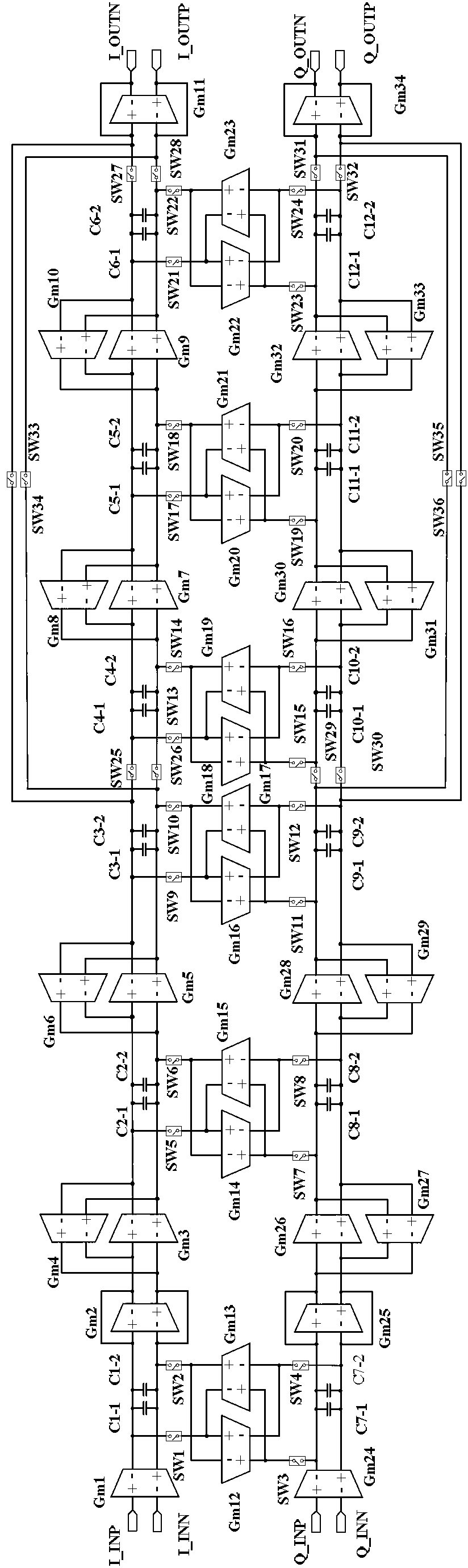
[0026] Embodiment 1: see figure 1, the reconfigurable Gm_C filter is composed of a five-step ladder-shaped jump-coupled low-pass filter with the same structure for both I and Q channels, a transconductance gyrator group and a digital switch located outside the channel. Among them, the I-way five-step ladder-shaped coupling-hopping low-pass filter is composed of a transconductance operational amplifier Gm1, an input-side analog resistor Gm2, a first transconductance gyrator 1 to a first transconductance gyrator 4, an output-side analog resistor Gm11, and capacitors 1 to 4. The first transconductance gyrator is composed of transconductance operational amplifiers Gm3 and Gm4; the first transconductance gyrator two is composed of transconductance operational amplifiers Gm5 and Gm6; the first transconductance gyrator three is composed of transconductance operational amplifiers Composed of Gm7 and Gm8, the first transconductance gyrator four is composed of transconductance operation...

Embodiment 2

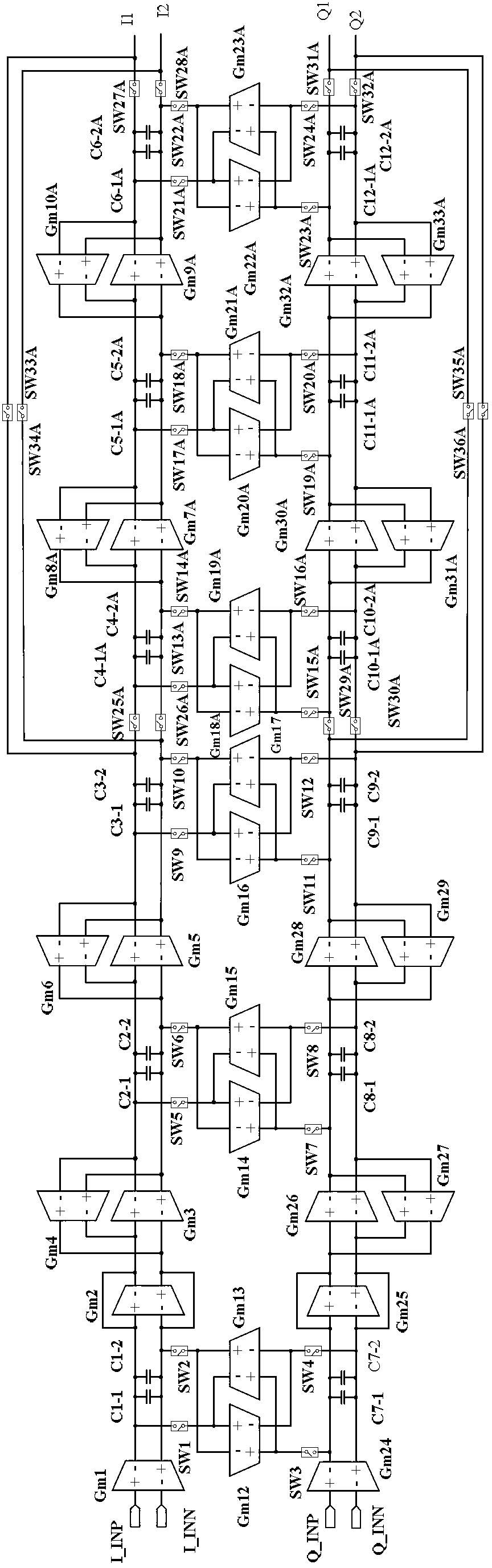
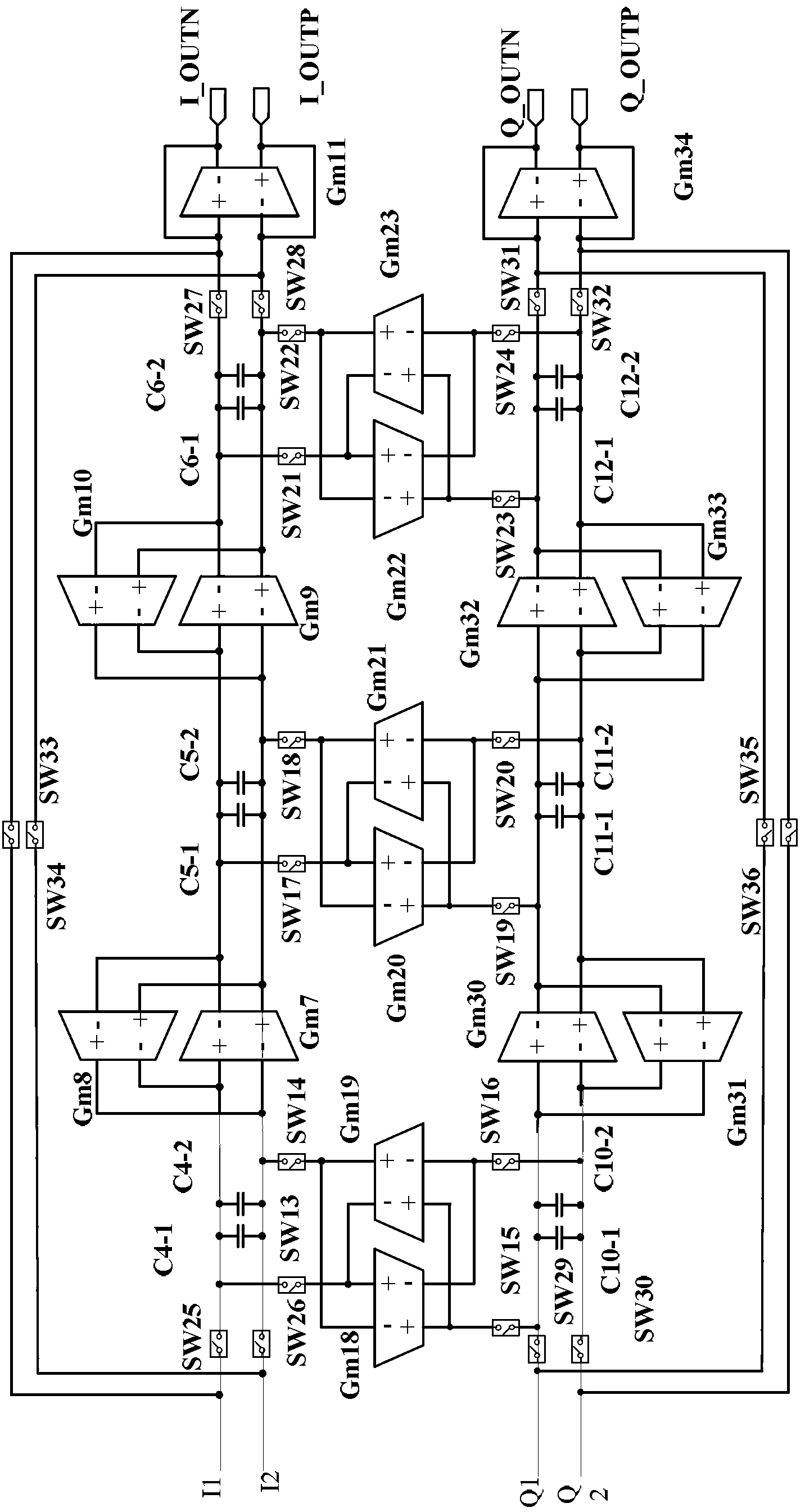
[0034] Example 2: see figure 2 with image 3 , the reconfigurable Gm_C filter is composed of a seven-step coupler-hopping low-pass filter with the same structure for both I and Q channels, a transconductance gyrator group and a digital switch located outside the channel. The difference from Example 1 is:

[0035] The I-way seven-step coupler-hopping low-pass filter is composed of a transconductance operational amplifier Gm1, an input-side analog resistor Gm2, a first transconductance gyrator, a first transconductance gyrator two, and a transconductance operational amplifier Gm7A and Gm8A. 1. Transconductance gyrator 5. The first transconductance gyrator composed of transconductance operational amplifiers Gm9A and Gm10A 6. The first transconductance gyrator 3. The first transconductance gyrator 4. Output side analog resistance Gm11, capacitor 1~capacitor 3. Capacitor four A ~ capacitor six A, capacitor four ~ capacitor six; capacitor four A is composed of capacitor C4-1A, C4...


PUM


Abstract

The invention discloses a reconfigurable Gm_C filter circuit which comprises an I path in-phase signal channel, a Q path orthogonal signal channel and a transconductance gyrator group outside the channels. The circuit is characterized in that the I path in-phase signal channel and the Q path orthogonal signal channel are same Gm_C low pass filters with a trapezoid jump coupling structure; symmetrical capacitive elements in the two signal channels are connected through one transconductance gyrator in the transconductance gyrator group outside the channels; and each of the differential input end and the differential output end of each transconductance gyrator in the transconductance gyrator group outside the channels are connected with a digital switch. According to reconfigurable Gm_C filter circuit disclosed by the invention, a Gm_C filter is configured to two working modes, namely, a plurality of band-pass filters and low pass filters through the digital switches, so that switching between the plurality of band-pass filters and low pass filters of the Gm_C filter in the on-chip trapezoid jump coupling structure is realized. Configuration switching among three-order, five-order, seven-order or even higher order of the filters is realized, and the reconfigurable Gm_C filter circuit can be widely applied to electronic communication systems.

Description

technical field [0001] The invention relates to a filter circuit, in particular to a reconfigurable Gm_C filter circuit. Background technique [0002] A filter is a two-port network that is selective to the frequency of the input signal. Its amplitude-frequency response includes pass band, transition band and stop band, which allows the signal in the pass band to pass through with relatively small attenuation, the signal in the transition band is attenuated to different degrees, and the signal in the stop band After being suppressed by a large degree of attenuation, the signal will not only change its amplitude according to the frequency after passing through the filter, but also its phase characteristics will also be shaped to a certain extent. [0003] With the continuous progress of information technology and integrated circuit technology, active filters are more and more widely used in wireless transceivers. At present, active filters mainly include Gm-C filters, RC fi...

Claims


Application Information

Patent Timeline
Patent Type & Authority Applications(China)
IPC IPC(8): H03H11/04
Inventor 韦学强范麟万天才刘永光李明剑徐骅
Owner CHONGQING SOUTHWEST INTEGRATED CIRCUIT DESIGN
Why Eureka
Try Eureka