Supercharge Your Innovation With Domain-Expert AI Agents!

Endoscope optical system

A technology for optical systems and endoscopes, applied in the direction of endoscopes, optics, optical components, etc., can solve problems such as larger diameters

Inactive Publication Date: 2013-07-31
OLYMPUS CORP
View PDF9 Cites 17 Cited by
  • Summary
  • Abstract
  • Description
  • Claims
  • Application Information

AI Technical Summary

Problems solved by technology

Therefore, there is a problem that the overall diameter of the distal end of the endoscope becomes large.

Method used


Image

  • Endoscope optical system
  • Endoscope optical system
  • Endoscope optical system

Examples


Embodiment

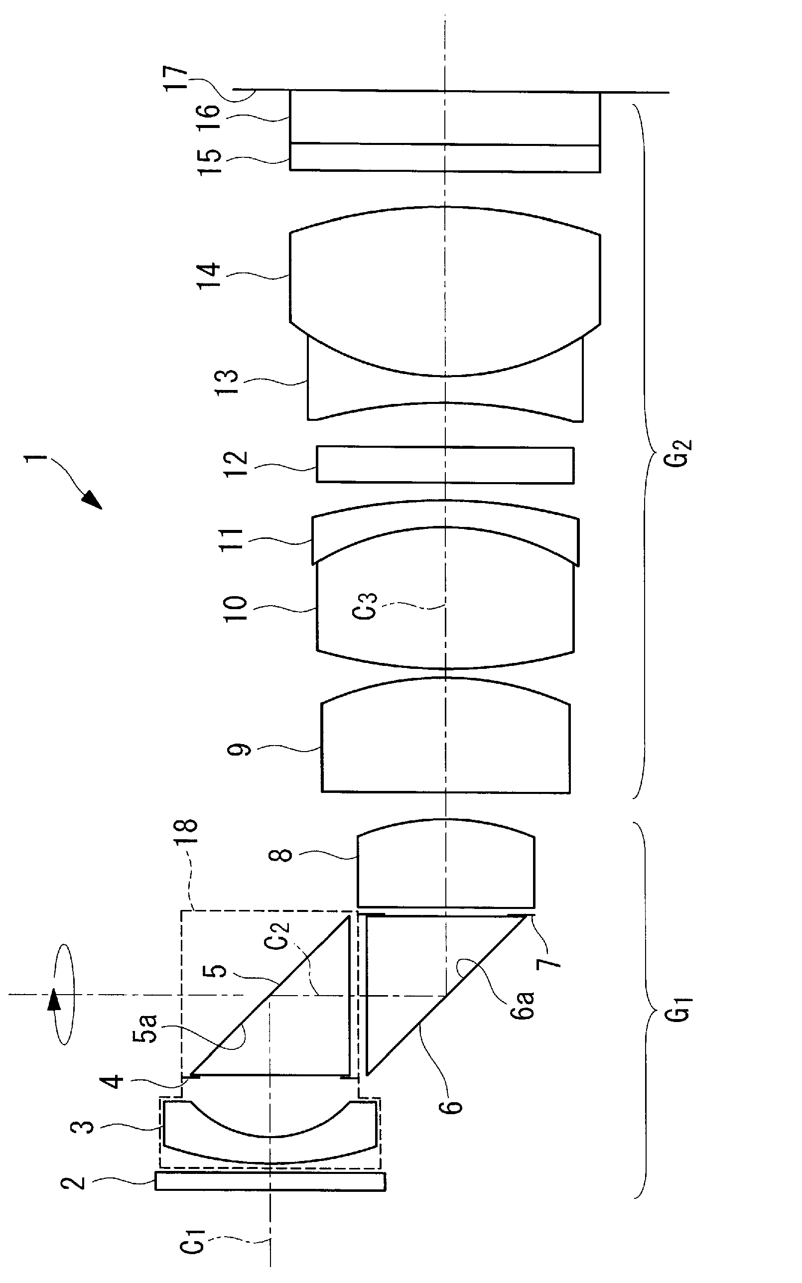
[0099] Next, examples of the endoscope optical system 1 according to the first embodiment of the present invention will be described below with reference to the drawings.

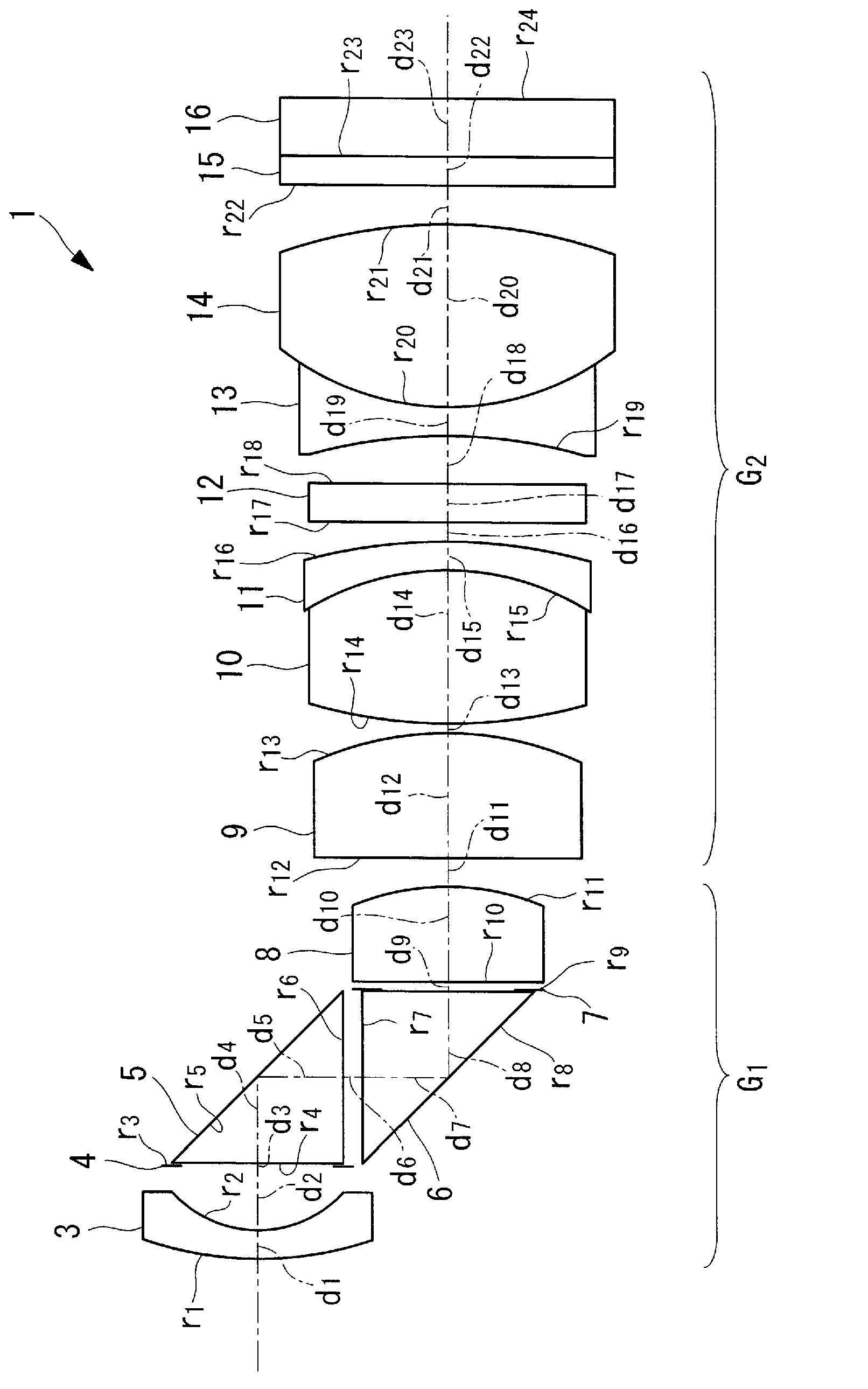
[0100] Such as image 3 As shown, the optical system 1 for an endoscope of this embodiment includes a front lens group G1 and a rear lens group G2.

[0101] The front lens group G1 includes a negative lens 3 composed of a concave-convex lens, a stray light blocking diaphragm 4, two triangular prisms 5, 6, a brightness diaphragm 7, and a positive lens 8 composed of a plano-convex lens.

[0102] The rear lens group G2 includes a plano-convex lens 9 , a cemented lens composed of two convex lenses 10 and a concave-convex lens 11 , a plate glass 12 , a cemented lens composed of two concave lenses 13 and two convex lenses 14 , and a plate glass 16 .

[0103] The lens data for the above lenses are shown below.

[0104]

[0105]

[0106] Additionally, in this example,

[0107] (Np1+Np2A) / 2=2.01

[0108] D...


PUM


Abstract

In order to keep the diameter dimension of the tip of an endoscope small while making the direction of view of the endoscope variable and obtain an endoscopic image with a good image quality, provided is an endoscope optical system (1) equipped with, in order from the object side, a negative lens (3) which collects light incident along an incident light axis (C1); a first prism (5) which deflects and emits the light collected by the negative lens (3) in a direction along a first axis line (C2) approximately orthogonal to the incident light axis (C1); a second prism (6) which has a reflection surface for deflecting the light emitted from the first prism (5) in the direction of a second axis line (C3) approximately orthogonal to the first axis line (C2) and is disposed to face the first prism (5); and a positive lens (8) which collects the light emitted from the second prism (6), wherein the negative lens (3) and the first prism (5) being provided to be rotatable about the first axis line (C2) with respect to the second prism (6).

Description

technical field [0001] The present invention relates to an optical system for an endoscope. Background technique [0002] Conventionally, there is known an endoscope that can change the direction of the field of view of the endoscope by swinging or rotating a reflector or a prism disposed at the tip of the endoscope (for example, refer to Patent No. Document 1 and Patent Document 2). [0003] Patent Document 1: Specification of US Patent No. 6638216 [0004] Patent Document 2: Japanese Patent Laid-Open No. 2006-201796 [0005] Patent Document 3: Japanese Patent No. 4503535 [0006] However, in the case of Patent Document 1, the reflecting mirror is arranged in the endoscope at a position radially offset from the optical axis of another optical system, and moves in the radial direction in the endoscope. Therefore, there is a problem that the size of the distal end portion of the endoscope increases in the radial direction. In addition, since the size of other optical sys...

Claims


Application Information

Patent Timeline
IPC IPC(8): G02B13/04A61B1/00G02B23/26
CPCA61B1/05G02B5/04A61B1/00183G02B23/2446G02B27/0025A61B1/00096
Inventor 片仓正弘
Owner OLYMPUS CORP
Features
  • R&D
  • Intellectual Property
  • Life Sciences
  • Materials
  • Tech Scout
  • Unparalleled Data Quality
  • Higher Quality Content
  • 60% Fewer Hallucinations
Learn More