Laser-driving X-ray medical imaging device and imaging method thereof

An imaging method and medical imaging technology, applied in medical science, equipment for radiological diagnosis, diagnosis, etc., can solve the problems of complex operation, low imaging resolution, high cost, etc., and achieve the effect of improving resolution

Inactive Publication Date: 2013-08-07
陈黎明
View PDF10 Cites 2 Cited by
  • Summary
  • Abstract
  • Description
  • Claims
  • Application Information

AI Technical Summary

Problems solved by technology

[0004] Synchrotron radiation light sources have been proven to be widely used in various researches. However, due to their huge equipment, complex operations, high costs, and inability to perform physical examinations, they have great limitations in practical medical applications.
The source size of the X-ray light tube for ordinary physical examination is too large, usually 200um-300um, and the imaging resolution is not high. It can only distinguish cancer cells with a diameter of 1cm, and it cannot be applied to medical early diagnosis and early treatment of medical examination.
The source size of the micron X-ray tube may also be made into more than ten microns for long-term imaging diagnosis, but the X-ray flux generated by the source is very low and is not suitable for physical examination.

Method used


Image

  • Laser-driving X-ray medical imaging device and imaging method thereof
  • Laser-driving X-ray medical imaging device and imaging method thereof
  • Laser-driving X-ray medical imaging device and imaging method thereof

Examples


Embodiment 1

[0017] refer to figure 1 Describe a specific embodiment of the imaging method of the X-ray medical imaging device according to the present invention, the method includes:

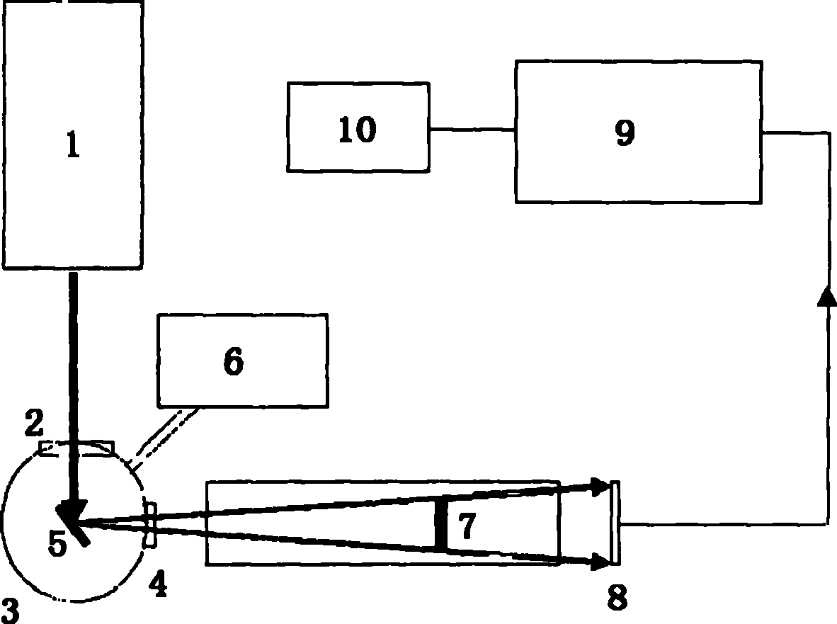
[0018] 1) Using laser 1 to output a laser pulse beam with an output frequency of 100 Hz, an energy of 600 mJ, a center wavelength of 800 nm, and a pulse width of 60 fs;

[0019] 2) The above-mentioned laser beam passes through the focusing optical element 2 and is focused into a spot with a size of 10um, and the average intensity of the laser in the focusing area is 3×10¹⁸W / cm2;

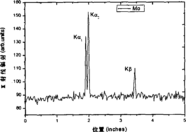
[0020] 3) lead the focused laser beam to the Mo target 5 located in the target chamber 3, and interact with the Mo target 5 at the focal point to generate Mo K-shell X-rays;

[0021] 4) Filter out the interference of low-energy X-rays and electrons through the Mo sheet 4;

[0022] 5) Perspective imaging via the biological imaging sample 7 on the console;

[0023] 6) The image formed by the Fujifilm SR-2025 imaging plate 8 is re...

Embodiment 2

[0031] refer to figure 1 A specific embodiment of the X-ray medical imaging device according to the present invention is described, and the imaging device includes:

[0032] 1) Ti:sapphire laser 1, which can output laser pulse beams, the laser can be, for example, a 10TW Ti:sapphire laser;

[0033] 2) focusing optical element off-axis parabolic mirror (OAP) 2, used to focus the laser beam output by the laser, the focusing optical element can be, for example, an off-axis parabolic mirror (OAP) or a telephoto lens;

[0034] 3) Mo target 5, located in the target chamber 3;

[0035] 4) Mo sheet 4, used to filter out the interference of low-energy X-rays and electrons;

[0036] 5) Imaging plate (Fujifilm SR-2025 Image Plates) 8;

[0037] 6) IP reader (Fujifilm 1800 II Scanner) 9, which is used to convert the information on the imaging plate into visual image information, and read and analyze it by the computer 10, so as to obtain a clear perspective image of the imaging object; ...


PUM


Abstract

The invention provides an imaging method of an X-ray medical imaging device. The method comprises: outputting a laser pulse beam with a frequency of 100 Hz, energy of 600 mJ, a central wave length of 800 nm and a pulse width of 60 fs; focusing the laser pulse beam through an off-axis parabolic mirror (OA0), wherein the diameter of the a focal spot is 10 mu m; shooting the focused laser beam onto a solid molybdenum target, and generating a dozen-keV hard X-ray through the interaction of the focused laser beam and the solid target in the focus area; and utilizing the hard X-ray to perform organism imaging. The invention also provides the X-ray medical imaging device.

Description

technical field [0001] The invention relates to a laser-driven ultrafast hard X-ray medical imaging device and an imaging method thereof. Background technique [0002] In recent years, the number of people suffering from cancer has been increasing every year, and it has reached 2.6 million people per year. The number of people who die from cancer every year is now more than 1.8 million, and the average five-year mortality rate is nearly 30%. By 2015, the mortality rate is expected to rise to 50%, with a total of more than 5 million people / year. Due to the shortage of doctors and equipment for diagnosis and treatment, the society has to face the coming cancer disaster. However, our current methods of treating cancer include chemical drug therapy, surgical treatment and radiation therapy for cancer tumors, all of which do great harm to the human body, so the importance of early diagnosis is far greater than that of treatment. [0003] Taking the diagnosis of breast cancer as...

Claims


Application Information

Patent Timeline
Patent Type & Authority Applications(China)
IPC IPC(8): A61B6/00
Inventor 陈黎明
Owner 陈黎明
Why Eureka
Try Eureka