
Full-automatic non- backer pipe cutting machine tool and operation method thereof

A fully automatic, backing technology, used in pipe shearing devices, shearing devices, shearing machine equipment, etc., can solve the problems of severe wear of backing, severe wear of feeding chucks, and low dimensional accuracy of workpieces.

Active Publication Date: 2013-08-07
余姚市宏宇机械设备厂
View PDF7 Cites 0 Cited by
  • Summary
  • Abstract
  • Description
  • Claims
  • Application Information

AI Technical Summary

Problems solved by technology

The pipe cutting machine includes a feeding device. When the traditional feeding device is feeding, after the front chuck is loosened, the rear cylinder piston advances to make the feeding chuck clamp the workpiece, and then the servo drives the rear cylinder body to push forward to the required position, etc. After the front cylinder is clamped, the piston of the rear cylinder retreats, and then the servo is used to return the rear cylinder to the original position; the feeding action is to feed when the workpiece is not rotating, and the feeding chuck is always locked to the workpiece, and the front chuck is clamped to drive the feeding instantly. The chuck rotates, which wears the feeding chuck severely, and there are scratch marks on the surface of the workpiece. The length of the feeding material must be controlled by collision with the backing. The backing is severely worn and the dimensional accuracy of the workpiece is low.

Method used


Image

  • Full-automatic non- backer pipe cutting machine tool and operation method thereof
  • Full-automatic non- backer pipe cutting machine tool and operation method thereof
  • Full-automatic non- backer pipe cutting machine tool and operation method thereof

Examples


Embodiment Construction

[0045] The present invention will be further described below in conjunction with the accompanying drawings and specific embodiments, but not as a limitation of the present invention.

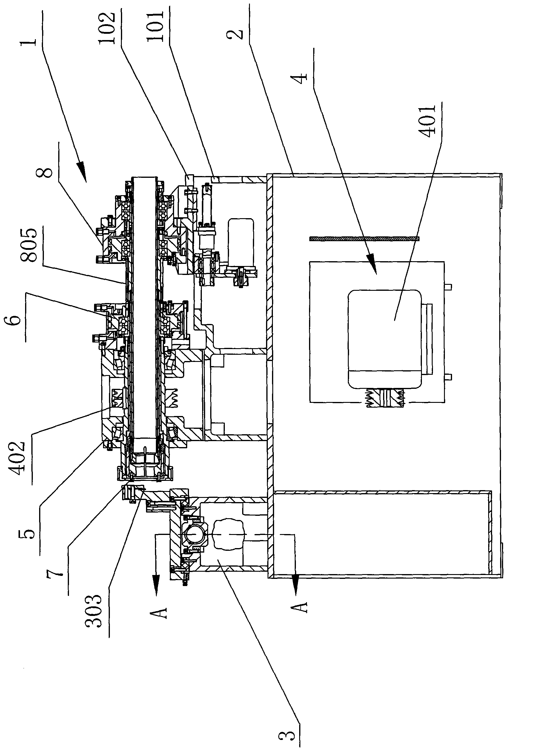
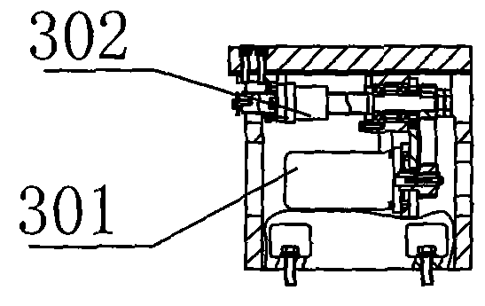
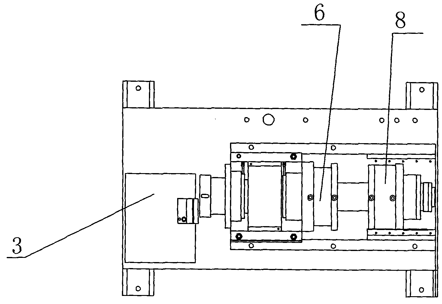
[0046] like Figure 1-1 to Figure 5-2 As shown, a fully automatic pipe cutting machine tool without backing is used for cutting tubular workpieces 20, and includes a main machine 1, a machine tool installation platform 2 and a tool box 3. The tool box 3 is arranged in front of the main engine 1, and the main engine 1 includes a lathe base 101, a drive motor assembly 4, a main shaft assembly 5, a front cylinder 6, and a front chuck clamping structure 7; the drive motor assembly 4 includes a drive motor 401 and a shaft pulley 402, the spindle assembly 5 includes a spindle box 501, a hollow spindle 502 and a cylindrical pin A503, and the front cylinder 6 includes a front cylinder body 601, a front cylinder piston 602, a front cylinder shaft 603, a front cylinder air pipe joint 604 and a front chuck...


PUM


Abstract

The invention discloses a full-automatic non-backer pipe cutting machine tool and an operation method thereof and belongs to the technical field of machine tools for cutting pipes. The pipe cutting machine tool comprises a main machine, a machine tool mounting platform and a feed box. The main machine comprises a machine tool base, a drive motor component, a spindle component, a front air cylinder, a front chuck clamping structure, a rear air cylinder, a feed clamping structure and a feed power structure. The feed clamping structure comprises a feed chuck, a feed chuck stay pipe, a feed steel jacket and a feed steel jacket push pipe. The front chuck clamping structure comprises a front chuck, a main push sleeve, a front chuck nut and a main push pipe. The rear air cylinder comprises a rear air cylinder piston, a spline sleeve, a spline shaft, a cylindrical pin B, a spline nut B and a tail shaft sleeve. The tail shaft sleeve is in threaded fixed connection with the tail of the feed chuck stay pipe; and the rear end of the cylindrical pin B is fixedly connected with the front end of the tail shaft sleeve, and the front end of the cylindrical pin B is in inserted connection with the spline nut B. The operation method of the pipe cutting machine is detailed simultaneously. The full-automatic non-backer pipe cutting machine tool and the operation method thereof have the advantages that feed can be performed during rotation of workpieces, and the working efficiency is improved.

Description

technical field [0001] The invention relates to a pipe cutting machine tool and an operating method thereof, in particular to a fully automatic pipe cutting machine tool without a backing and an operating method thereof, and belongs to the technical field of machine tools used for pipe cutting. Background technique [0002] The pipe cutting machine is a device for cutting tubular workpieces. The pipe cutting machine includes a feeding device. When the traditional feeding device is feeding, after the front chuck is loosened, the rear cylinder piston advances to make the feeding chuck clamp the workpiece, and then the servo drives the rear cylinder body to push forward to the desired position, etc. After the front cylinder is clamped, the piston of the rear cylinder retreats, and then the servo is used to return the rear cylinder to the original position; the feeding action is to feed when the workpiece is not rotating, and the feeding chuck is always locked to the workpiece, ...

Claims


Application Information

Patent Timeline
IPC IPC(8): B23D21/00B23Q7/00
Inventor 刘志军刘晓晓
Owner 余姚市宏宇机械设备厂
Learn More