
Double-point compressing device

A technology of a pressing device and a power device, which is applied to workpiece clamping devices, manufacturing tools, etc., can solve the problems of large static friction, inconsistent downward pressure on the workpiece, and inability to perform relative motion, and achieves the effect of improving operation speed and production efficiency.

Active Publication Date: 2013-08-07
GOERTEK INC
View PDF5 Cites 5 Cited by
  • Summary
  • Abstract
  • Description
  • Claims
  • Application Information

AI Technical Summary

Problems solved by technology

The compression device with the above structure can only compress the workpiece at one point. If it is necessary to compress the workpiece at two points, for example, it is necessary to compress the workpiece diagonally or the middle of both sides of the workpiece, which cannot be realized by one device; And the pressing device of the above structure can only be pressed along a straight line direction, and cannot realize the pressing that deviates from the telescopic direction of the guide arm.
In addition, in order to achieve fast operation, the length of the power device driving the guide arm to expand and contract is usually fixed in the pressing device in the prior art. After the workpiece is placed, the guide arm stretches out to compress the workpiece. After the workpiece is processed, The guide arm is retracted to facilitate the removal of the workpiece, so the size of the workpiece changes and the distance between the pressing points is too large or too small, and the pressing cannot be achieved
[0003] In addition, in the pressing device in the prior art, the pressing distance of the pressing element is constant, and when the thickness of the workpiece changes, the pressing force on the workpiece is inconsistent, too large or too small, resulting in difficulty in subsequent workpiece processing
For example: in the case where two workpieces need to be pressed and then aligned, it may be that the static friction between the two workpieces is too large due to excessive pressure, and relative movement cannot be performed, resulting in ineffective alignment

Method used


Image

  • Double-point compressing device
  • Double-point compressing device

Examples


Embodiment Construction

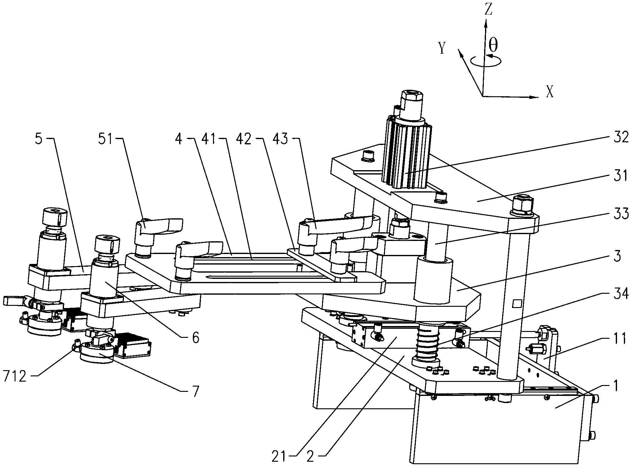
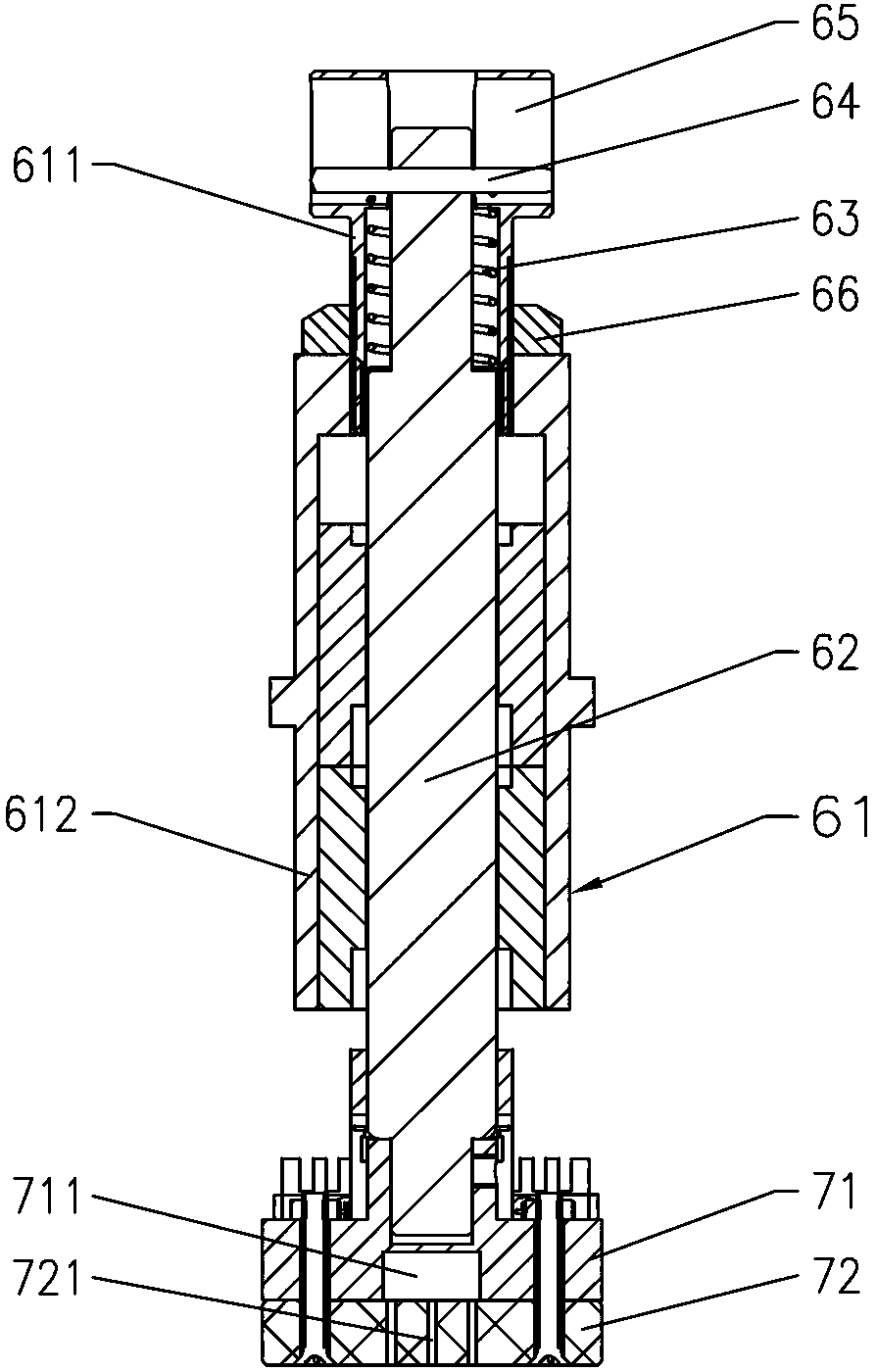
[0026] Such as figure 1 with figure 2 Shown, a two-point pressing device. See X, Y, Z directions in the three-dimensional coordinate system figure 1 , where the X direction and the Y direction are two directions perpendicular to each other in the horizontal plane, and the Z direction is the direction perpendicular to the horizontal plane. The specific structure includes the following parts.

[0027] First include base 1. The X-direction mobile platform 2 driven by the first power device 21 is installed on the base 1. In this implementation process, the first power device 21 adopts a cylinder, and a linear guide rail is installed between the X-direction mobile platform 2 and the base 1. The first power The device 21 is fixed on the X-direction moving platform 2 , and the end of the push rod of the first power device 21 is fixed on the protruding retaining wall 11 of the base 1 .

[0028] The Z-direction mobile platform 3 driven by the second power unit 32 is installed on ...


PUM


Abstract

The invention discloses a double-point compressing device which comprises a base, an X-direction moving platform mounted on the base and driven by a first power device, a Z-direction moving platform mounted on the X-direction moving platform and driven by a second power device, an X-direction telescopic arm mounted on the Z-direction moving platform, a first positioning and locking piece used for adjusting the retractable length of the X-direction telescopic arm and mounted on the Z-direction moving platform, two Theta-angle rotating arms and a second positioning and locking piece used for adjusting the rotary angles of the Theta-angle rotating arms, compressing elements mounted at the end parts of the two Theta-angle rotating arms, and pressure heads mounted at the bottoms of the elastic down-pressing pieces, wherein each compressing element comprises elastic down-pressing pieces fixed at the end parts of the Theta-angle rotating arms. According to the invention, compressing distance can be conveniently adjusted according to different sizes of the workpieces; double-point compressing is achieved, the distance between the two compressing elements can also be adjusted, and two compressing ways of compressing corners or middle point by workpieces with different sizes can be achieved.

Description

technical field [0001] The invention relates to a pressing device used in the process of workpiece processing and installation. Background technique [0002] The clamping device is an important part in the installation and processing of workpieces. The usual structure of the pressing device in the prior art is: it includes a guide arm driven by a power device that can move horizontally and vertically, and a pressing element is arranged at the end of the guide arm. The compression device with the above structure can only compress the workpiece at one point. If it is necessary to compress the workpiece at two points, for example, it is necessary to compress the workpiece diagonally or the middle of both sides of the workpiece, which cannot be realized by one device; And the pressing device of the above structure can only be pressed along a straight line direction, and cannot realize the pressing that deviates from the telescopic direction of the guide arm. In addition, in or...

Claims


Application Information

Patent Timeline
IPC IPC(8): B25B11/00
Inventor 贺文佳苏斌
Owner GOERTEK INC
Learn More